Download
1 / 18
180 likes | 356 Views
NSTX. Supported by. Snowflake divertor configuration in NSTX. College W&M Colorado Sch Mines Columbia U CompX General Atomics INEL Johns Hopkins U LANL LLNL Lodestar MIT Nova Photonics New York U Old Dominion U ORNL PPPL PSI Princeton U Purdue U SNL Think Tank, Inc.

E N D
NSTX Supported by Snowflake divertor configuration in NSTX College W&M Colorado Sch Mines Columbia U CompX General Atomics INEL Johns Hopkins U LANL LLNL Lodestar MIT Nova Photonics New York U Old Dominion U ORNL PPPL PSI Princeton U Purdue U SNL Think Tank, Inc. UC Davis UC Irvine UCLA UCSD U Colorado U Illinois U Maryland U Rochester U Washington U Wisconsin V. A. Soukhanovskii (LLNL) Acknowledgements: NSTX Team Culham Sci Ctr U St. Andrews York U Chubu U Fukui U Hiroshima U Hyogo U Kyoto U Kyushu U Kyushu Tokai U NIFS Niigata U U Tokyo JAEA Hebrew U Ioffe Inst RRC Kurchatov Inst TRINITI KBSI KAIST POSTECH ASIPP ENEA, Frascati CEA, Cadarache IPP, Jülich IPP, Garching ASCR, Czech Rep U Quebec NSTX Results Review Princeton, NJ Wednesday, 1 December 2010
Acknowledgements D. D. Ryutov, T. D. Rognlien, M. V. Umansky (LLNL), R. E. Bell, D. A. Gates, A. Diallo, S. P. Gerhardt, R. Kaita, S. M. Kaye, E. Kolemen, B. P. LeBlanc, R. Maqueda, J. E. Menard, D. Mueller, S. F. Paul, M. Podesta, A. L. Roquemore, F. Scotti (PPPL), J.-W. Ahn, R. Maingi, A. McLean (ORNL), D. Battaglia, T. K. Gray (ORISE), R. Raman (U Washington), S. A. Sabbagh (Columbia U) Supported by the U.S. DOE under Contracts DE-AC52-07NA27344, DE AC02-09CH11466, DE-AC05-00OR22725, DE-FG02-08ER54989.
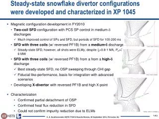
NSTX studies suggest the snowflake divertor configuration may be a viable divertor solution for present and future tokamaks • Steady-state snowflake (up to 600 ms, many tE’s) • Good H-mode confinement • Reduced core carbon concentration • Significant reduction in peak divertor heat flux • Potential to combine with radiative divertor for increased divertor radiation • Planned future efforts with the snowflake divertor: • Improved magnetic control • Pedestal peeling-balooning stability • ELM heat and particle deposition profiles • Divertor impurity source distribution • Divertor and upstream turbulence (blobs)
Snowflake divertor with three coils (w/ reversed PF1B) from a medium-d discharge ELMy H-mode with steady-state snowflake Snowflake with three coils (w/ reversed PF1B) from a high-d discharge Best steady-state SFD, no OSP sweeping through CHI gap Fiducial like-performance, basis for integration with advanced scenarios Standard divertor (medium and high-d) is transformed into snowflake divertor using three divertor coils
Significant core impurity reduction and good H-mode confinement properties with snowflake divertor • 0.8 MA, 4 MW H-mode • k=2.1, d=0.8 • CoreTe ~ 0.8-1 keV, Ti ~ 1 keV • bN~ 4-5 • Plasma stored energy~ 250 kJ • H98(y,2) ~ 1 (from TRANSP) • Core carbon reduction due to • Medium-size Type I ELMs • Edge source reduction • In ELM-free discharges with snowflake divertor, carbon concentration reduction also observed and attributed to edge source reduction
Strong signs of partial strike point detachment are observed in snowflake divertor • Heat and ion fluxes in the outer SP region decreased • Divertor recombination rate and radiated power are increased
Snowflake divertor configurations obtained in NSTX confirm analytic theory and modeling Standard Snowflake fexp Bp
Snowflake divertor appears to alter pedestal stability and impulsive divertor heat loads due to ELMs • Increased magnetic shear predicted in snowflake divertor • In NSTX • Snowflake sometimes does not survive ELMs • Convective ELM heat flux follows magnetic surfaces, peak still reduced • Snowflake divertor triggered ELMs from a suppressed ELM state (lithium) • Snowflake divertor effect on ELMs in TCV (F. Piras et al., PRL 2010) • Type I ELMs in snowflake divertor • increased size • decreased frequency
Different edge profiles are measured during the ELMy snowflake phase • Carbon concentration reducedby 10-20 % in the pedestal region • ne reduced in top pedestal region (due to carbon reduction?)
Snowflake divertor alters divertor heat load deposition profile due to ELMs
Snowflake divertor heat flux consistent with NSTX divertor heat flux scalings 0.8 MA * * * flux expansion • Snowflake divertor (*): PSOL~3-4 MW, fexp~40-80, qpeak~0.5-1.5 MW/m2 T. K. Gray et. al, EX/D P3-13, IAEA FEC 2010 V. A. Soukhanovskii et. al, PoP 16, 022501 (2009)
Attractive divertor geometry properties predicted by theory in snowflake divertor configuration Exact snowflake divertor snowflake-minus snowflake-plus D. D. Ryutov, PoP 14, 064502 2007 • Snowflake divertor • Second-order null • Bp ~ 0 and grad Bp ~ 0; Bp ~ r2 (Cf. first-order null: Bp ~ 0; Bp ~ r) • Obtained with existing divertor coils (min. 2) • Exact snowflake topologically unstable • Predicted properties (cf. standard divertor) • Larger low Bp region around X-point • Larger plasma wetted-area Awet (flux expansion fexp) • Larger X-point connection length Lx • Larger effective divertor volume Vdiv • Increased edge magnetic shear • Experiments • TCV (F. Piraset. al, PRL 105, 155003 (2010))
Divertor profiles show low heat flux, broadened C III and C IV radiation zones in the snowflake divertor phase • Heat flux profiles reduced to nearly flat low levels, characteristic of radiative heating • C III and C IV emission profiles broaden • High-n Balmer line spectroscopy and CRETIN code modeling confirm outer SP detachment with Te ≤ 1.5 eV, ne ≤ 5 x 10²⁰ m-3 • Also suggests large reduction of carbon physical and chemical sputtering rates
Snowflake divertor reduces heat flux and screens impurities as good as radiative divertor • Ip=0.9 MA, PNBI = 4 MW, PSOL = 3 MW • Comparison of standard divertor, snowflake divertor, and radiative divertor with CD4 puffing (onset at 0.5 s) • Peak heat flux reduced by 60-75 % by radiative divertor and snowflake divertor • Divertor Prad increased by up to 50 % in snowflake divertor, less in radiative divertor • Neutral compression (Pdiv/ Pmid) higher in snowflake and radiative divertors • Pedestal impurity concentration reduced in snowflake and radiative divertors
2D multi-fluid edge transport code UEDGE is used to study snowflake divertor properties Standard Snowflake • Fluid (Braginskii) model for ions and electrons • Fluid for neutrals • Classical parallel transport, anomalous radial transport • Core interface: • Te = 120 eV • Ti = 120 eV • ne = 4.5 x 10¹⁹ • D = 0.25 m2/s • ce,i = 0.5 m2/s • Rrecy = 0.95 • Carbon 3 %
Radiated power is broadly distributed in the outer leg of snowflake divertor UEDGE model
UEDGE model shows a trend toward detachment in snowflake divertor outer leg (cf. standard divertor) In the snowflake divertor outer strike point region: • Te and Tireduced • Divertor peak heat flux reduced • Particle flux low UEDGE model Experiment