Download
1 / 14
140 likes | 343 Views
Beams produced at LISOL by laser ionization after thermalisation of energetic ions in a gas cell. M. Facina, J. Gentens, M. Huyse, Y. Kudryavtsev, P. Van den Bergh and P. Van Duppen Instituut voor Kern- en Stralingsfysica, K.U.Leuven Celestijnenlaan 200D, B-3001, Leuven, Belgium

E N D
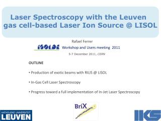
Beams produced at LISOL by laser ionization after thermalisation of energetic ions in a gas cell M. Facina, J. Gentens, M. Huyse, Y. Kudryavtsev, P. Van den Bergh and P. Van Duppen Instituut voor Kern- en Stralingsfysica, K.U.Leuven Celestijnenlaan 200D, B-3001, Leuven, Belgium http://www.fys.kuleuven.ac.be/iks/lisol/index.html • The LISOL laser ion source: • new front-end • survey of off- and on-line results • Examples of decay spectroscopy experiments • Further optimizations: Ion Catcher framework • Conclusion and outlook
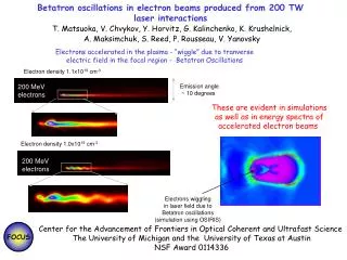
Louvain-la-Neuve Radioactive Beam Facility target CYCLONE 110 CYCLONE 30 ECR ion sources 200 mA 30 MeV p CYCLONE 44 LEDA ARES lasers LISOL
Lay out of the gas cell heavy-ion fusion 238U - fission
New front end • -better differential pumping • -more space • ion source • spig • better control on position • cyclotron beam • ion source • lasers • spig • beam energy degraders
Survey of on- and off-line results • (*) low efficiency due to • missing stable Ru filament in the gas cell (laser tuning) • hole in the target (inspection after the run)
p (30 MeV) + 238U Ga Cu Ni Co cross section (mbarn) K.-H. Schmidt V. Rubchenya • 70 75 80 85 • Mass 10 pbarn: 78Ni Results for fission S. Franchoo et al., Phys. Rev. Lett, 81 (1998) 3100, Phys. Rev. C 64 (2001) 054308 W.F. Mueller et al., Phys. Rev. Lett. 83 (1999) 3612, Phys. Rev. C 61 (2000) 054308 K. Krouglov et al., submitted to EPJA
Further optimization (Ion Catcher network) How to reach efficiencies in the 10 % region? How to reach higher selectivity (now 50 – 500)? Are there primary beam intensity limitations? What is the fate of ions and atoms in a gas cell? • losses due to • ion – electron recombination • critical ion – electron density • ion – gas and ion – impurity interactions • atom – gas and atom – impurity interactions a possible solution electrical fields in the gas cell ! space – charge effects !
Ion-electron recombination Ar (500 mbar) gas lasers 58Ni (185 MeV) 0.1 ppA 15 pnA Vdissociation SPIG NiX impurity molecules
Ion - electron recombination gas Cyclotron pulse 40Ar Intensity (a.u.) 58Ni on-resonance 58Ni off-resonance 0 Time (s) lasers • Some observations • less than 0.1 % Ni ions survive, others neutralized • laser re-ionization up to 10% • 40Ar immediately present • but fast and effective recombination 58Ni 0.1 ppA 10 pnA
Ion - gas interactionsIon - Impurity interactions gas lasers filament hard sphere [H2O] ~ ppb Ni purified Ar NiArW NiAr2 NiW2 NiW3 NiAr NiW s s
Electrical fields in the gas cell + 240 V 58Ni + 30 V intensity (a.u.) + 3 V 0 V -2 2 6 10 time (ms) Important for: - collecting the electrons - dragging out the ions NO effect on: - ion - impurity interaction cross sections - ion - buffer gas interaction cross sections - ion - electron interaction cross sections
Application to the production of radioactive ion beams 3 case Incoming beam gas Q (#/cm .s) 16 16 1 0.5 atm He m 1 A 200 MeV O 3 10 x Q 8 12 2 0.5 atm Ar 5.6 x 10 fission-fragments per s 5.1 10 m (induced by 1 A 30 MeV protons) x + 242m 3 3 0.04 atm Ar 5.5 Am per s 2.6 10 m (induced by 5 A d) x + + 3 7 4 0.5 atm He 10 65 MeV Po 1.3 10 x + + + + + + + + + + + + + 1 d 2 5 - H.V. 4 3 8 10 5 0.5 atm He 10 650 MeV Rh 1.6 10 x e- removed What are the limits?
0.5 atm He a = 1.67 10-7 cm3s-1 n (cm-3) time (s) beam onoff 10-12 10-6 110+6 10-12 10-6 110+6 • neutralisation till the ion density is such that electrical fields can be applied • collect the electrons • collect the ions (enhances the selectivity) • re-ionize the atoms of interest by laser ionisation Conclusions and outlook • Ion Catcher network: • calculation of space charge effects in gas cells • characterization of the gas cell using 58Ni beam and evaporated atoms + LIS schemes for new elements • (electrical fields, limits in intensity) • gas cell for heavy-ion fusion evaporation reactions • (electrical fields) • RF-ion guide with segmented structure and emittance measurements • FRS-gas cell set-up (gas purity, experimental set-up) • on-line nuclear-physics experiments (fission and N=Z)