Fatigue striation morphology
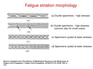
Fatigue striation morphology. (a) Ductile specimens – high stresses. (b) Ductile specimens – high stresses common also for small cracks. (c) Specimens cycled at lower stresses. (d) Specimens cycled at lower stresses.

Fatigue striation morphology
E N D
Presentation Transcript
Fatigue striation morphology (a) Ductile specimens – high stresses (b) Ductile specimens – high stresses common also for small cracks (c) Specimens cycled at lower stresses (d) Specimens cycled at lower stresses (Source: Campbell Laird “The influence of Metallurgical Structure on the Mechanisms of Fatigue Crack Propagation”, Fatigue Crack Propagation, ASTM STP 415, ASTM, 1967, p. 131)
Stage II crack - Crack tip plastic blunting and fatigue striation formation • Zero load • small tensile load • Maximum tensile load • Small compressive load • Maximum compressive load • Small tensile load (Source: Campbell Laird “The influence of Metallurgical Structure on the Mechanisms of Fatigue Crack Propagation”, Fatigue Crack Propagation, ASTM STP 415, ASTM, 1967, p. 131)
Crack tip profile in a copper single crystal cycled in tension-compression with a stress axis parallel to [001] (x250) (Source: Campbell Laird “The influence of Metallurgical Structure on the Mechanisms of Fatigue Crack Propagation”, Fatigue Crack Propagation, ASTM STP 415, ASTM, 1967, p. 131)
Changes occurring at the crack tip during a fatigue cycle • Compression • Maximum tension • Compression • Crack tip in an annealed nickel specimen after 360 cycles at a strain range of 0.017 (N = 465) (x850) • Crack in a fully compressed aluminum specimen cycled at 0.02 (x350)
Fracture surface of a cold-worked copper specimen cycled at high strain showing striations and inter-striations (x4500) (Source: Campbell Laird “The influence of Metallurgical Structure on the Mechanisms of Fatigue Crack Propagation”, Fatigue Crack Propagation, ASTM STP 415, ASTM, 1967, p. 131)
Stage I FCG – plastic blunting (a) Zero stress (b) Maximum stress (c) Compressive stress (Source: Campbell Laird “The influence of Metallurgical Structure on the Mechanisms of Fatigue Crack Propagation”, Fatigue Crack Propagation, ASTM STP 415, ASTM, 1967, p. 131)