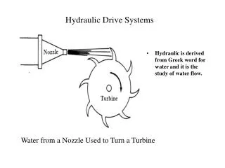
Hydraulic Drive Systems
Hydraulic Drive Systems. Hydraulic is derived from Greek word for water and it is the study of water flow. Water from a Nozzle Used to Turn a Turbine. Pressure. Pressure is developed in system when the fluid encounters some type of opposition. Figure B shows air pressure at sea level.

Hydraulic Drive Systems
E N D
Presentation Transcript
Hydraulic Drive Systems • Hydraulic is derived from Greek word for water and it is the study of water flow. Water from a Nozzle Used to Turn a Turbine
Pressure • Pressure is developed in system when the fluid encounters some type of opposition. • Figure B shows air pressure at sea level. Figure 2. Developing a Pressure on Fluids
Hydraulic Flow • The pressure developed in the robotic hydraulic system transforms energy into movement of the manipulator. • Velocity of a fluid is the avg. speed at which the fluid particles pass the give point, feet per minute, feet per second, or inches per second. • Flow rate of a fluid is the rate of the volume of a fluid passing a point at a given time. Gallons per minute. Figure 3. Oil Velocity as a Function of the Cross-Sectional Area of a Pipe
Figure 4. Pressure Drop. When a fluid is flowing there must be a condition of unbalance to cause the motion. Pressure is greatest at the point closest to the input of the fluid.
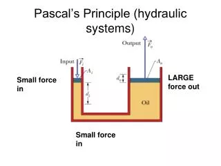
Bernoulli’s Principle Hydraulic fluid has two types of energy: Kinetic energy which develops from the weight and velocity of fluid Bernoulli’s Principle and Potential energy develops from pressure of fluid. Bernoulli’s Principle states that the sums of PE and KE at various points in a system must be constant if the flow rate is constant.
Figure 6. Schematic Diagram for Hydraulic Lines Pressure line are solid lines. This lines carries the main stream or flow of fluid. Pilot line (dashed) controls operational valves. Drain line (short dashed) function is carry leakage oil back to reservoirs.
Single-Acting Ram Cylinder • Cylinders are classified as linear actuators. • FOUR types of cylinders: Ram, Telescoping, double-acting, and double rod
Figure 14. Gear/Hydraulic Motor which receives pressure from fluid. The pressure causes the rotation of motor which develops a torque, providing a continuous rotational motion.