Download
1 / 51
520 likes | 838 Views
Learn about pneumatic and hydraulic drive systems, their components, design, and applications. Understand the properties of hydraulic systems and servo-drives. Study from lecture notes and textbooks with references.

E N D
Course Title : Pneumatic and Hydraulic drive Course Number : 315018571 Course Instructor Dr. Tariq Younes Prerequisites: 315018472 and 315018470 Email:tariqmograbi@yahoo.com
Course Description - Pneumatic drive systems and their components; - Electro- pneumatic systems; properties of hydraulic systems - Calculation and design of pneumatic and hydraulic drive motors; - Servo-drives and valves.
Textbook Fluid power with applications, Anthony Esposito , 7-th edition 2009 References http://www.hydraulicspneumatics.com 1. Lecture notes, course Pneumatic and Hydraulic Drives prepared by Dr. Mohamad Alia. 2.Fundamentals of pneumatic control engineering . A test book from FESTO. J.P. Hasbrink , R. Kobler, 1987, Germany 3. Hydraulics Basic Principles and Components. Didactic from Rexrroth H.Exner, R.Freity and others.OMEGN,2002.Germany
Learning Objectives 1. Explain what fluid power is. 2. Differentiate between the terms hydraulics and pneumatics. 3. Understand the difference between fluid power systems and fluid transport systems 4. Appreciate the history of the fluid power industry. 5. Discuss the advantages and disadvantages of fluid power. 6. Describe key applications of fluid power. 7. Specify the basic components of fluid power systems. 8. Appreciate the size and scope of the fluid power industry. 9. Identify the categories of personnel who are employed in the fluid power industry.
Introduction to Pneumatic and Hydraulic Drives What is Pneumatic (from the Greek pneumn for wind or breath).? Pneumatics is the discipline that deals with mechanical properties of gases such as pressure and density, and applies the principles to use compressed gas as a source of power to solve Engineering problems. What is Hydraulic (from the Greek words hydra for water and aulos for a pipe)? Hydraulics is the discipline that deals with the mechanical properties of liquids, and applies the principles to solve engineering problems.
Pneumatic and Hydraulic Drives or Fluid Power? What do we mean by Pneumatic and Hydraulic Drives ? Pneumatic and Hydraulic Drives - It is mainly considered with energy conversation [1] - Conversation pressure into force - Conversation of flow into speed [1] lecture notes
Fluid power Fluid power is the technology that deals with the generation, control, and transmission of power, using pressurized fluids. Fluid power is called hydraulics when the fluid is a liquid Fluid power is s called pneumatics when the fluid is a gas. Thus fluid power is the general term used for both hydraulics and pneumatic& Hydraulic systems The terms “fluid power” and “hydraulics and pneumatics” are synonymous
Spacecraft launcher Applications include landing gear, brakes, flight controls, motor controls and cargo loading equipment.
Fluid systems Fluid transport systems Fluid transport systems have as their sole objective the delivery of a fluid from one location to another to accomplish some useful purpose Example pumping stations for pumping water to homes Fluid power systems Fluid power systems are designed specifically to perform work. Example Operating fluid cylinder or fluid motor
Type of Fluids 1. Hydraulic systems A. Water Hydraulic system - Water hydraulics is expected to become more prevalent. - In Some applications water hydraulics should be used rather than oil ones. Disadvantages Advantages - abundance It freezes more readily - friendly It is not as good a lubricant - nonflammability It tends to rust preventive Improvement of water characteristics The water contains additives to improve lubricity and rust protection and prevent freezing where necessary.
B. Oil Hydraulic system Petroleum oils and synthetic oils The advantages and disadvantages of oil will be discussed later Why Liquids -Liquids provide a very rigid medium for transmitting power -They can operate under high pressures to provide huge forces and torques to drive loads with utmost accuracy and precision
Pneumatic systems Pneumatic systems use air as the gas medium because air is very abundant and can be readily exhausted into the atmosphere after completing its assigned task Why Air? - Spongy characteristics due to the compressibility of air. - They are less expensive to build and operate. - They can be used effectively in applications where Low pressures can be used because the loads to be driven do not require large forces.
HISTORY OF FLUID POWER Ancient historical accounts show that water was used for centuries to produce power by means of water wheels, and air was used to turn windmills and propel ships. Pascal’s law and Bernoulli’s law operate at the very heart of all fluid power.
The usage of compressed air : Reconstruction of the water organ of Ktesibios (Arens, 1960).
Beginning of Modern Era - in 1906 when a hydraulic system was developed to replace electrical systems for elevating and controlling guns on the battleship USS Virginia. - In 1926 the United States developed the first unitized, packaged hydraulic system consisting of a pump, controls, and actuator.
Today’s Fluid Power - Computerized fluid- power drives are available - Computer programming and bending process simulations are generated from a 3D model of the desired panel using CAD/CAM software. - microfluid power systems - nanotechnology
Hydraulic and Pneumatic systems and nanotechnology large-scale integrated microfluidic comparator containing 256 subnanoliter reaction chambers and 2056 microvalves
Electrical , pneumatic and hydraulic systems Let us consider the following task The task considered is how to lift a load by a distance of about 500 mm. Such tasks are common in manufacturing industries. B Direction Load A
Electrical solution Basic choices; - solenoid: the solenoid produces a linear stroke directly but its stroke is normally limited to a maximum distance of around 100 mm. - DC and AC motors : DC and AC motors are rotary devices and their outputs need to be converted to linear motion by mechanical devices such as wormscrews or rack and pinions. • The choice of motor depends largely on the speed control requirements. • A DC motor fitted with a tacho and driven by a thyristor drive can give excellent speed control, but has high maintenance requirements for brushes and commutator. • An AC motor is virtually maintenance free, but is essentially a fixed speed device (with speed being determined by number of poles and the supply frequency). • Speed can be adjusted with a variable frequency drive, but care needs to be taken to avoid overheating as most motors are cooled by an internal fan connected directly to the motor shaft. • We will assume a fixed speed raise/lower is required, so an AC motor driving a screwjack would seem to be the logical choice.
Electrical solution, based on three phase motor Operation a mechanical jack driven by an AC motor controlled by a reversing starter. Auxiliary equipment comprises two limit switches, and a motor overload protection device. There is no practical load limitation provided screw/gearbox ratio, motor size and contactor rating are correctly calculated.
Hydraulic solution A solution using hydraulic system can be realized using a hydraulic linear actuator (arm). It consists of a movable piston connected directly to the output shaft If fluid is pumped into pipe A the piston will move up and the shaft will extend; if fluid is pumped into pipe B, the shaft will retract. Hydraulic cylinder
- The maximum force available from the cylinder depends on fluid pressure and cross sectional area of the piston. - The system requires a liquid fluid to operate; expensive and messy and, consequently, the piping must act as a closed loop, with fluid transferred from a storage tank to one side of the piston, and returned from the other side of the piston to the tank. Fluid is drawn from the tank by a pump which produces fluid flow at the required 150 bar. - Cylinder movement is controlled by a three position changeover valve. - Speed control is easily achieved by regulating the volume flow rate to the cylinder (discussed in a later section). - Precise control at low speeds is one of the main advantages of hydraulic systems. - Travel limits are determined by the cylinder stroke and cylinders, generally, can be allowed to stall at the ends of travel so no overtravel protection is required. - The pump needs to be turned by an external power source; almost certainly an AC induction motor which, in turn, requires a motor starter and overload protection.
- Hydraulic fluid needs to be very clean, hence a filter is needed to remove dirt particles before the fluid passes from the tank to the pump. - One final point worth mentioning is that leaks of fluid from the system are unsightly, slippery (hence hazardous) and environmentally very undesirable A major failure can be catastrophic.
Pneumatic solution -The basic actuator is again a cylinder - The maximum force on the shaft being determined by air pressure and piston cross sectional area. - Operating pressures in pneumatic systems are generally much lower than those in a hydraulic systems; - Pneumatic systems therefore require larger actuators than hydraulic systems for the same load. - The valve delivering air to the cylinder operates in a similar way to its hydraulic equivalent. - One notable difference arises out of the simple fact that air is free; return air is simply vented to atmosphere. - Air is drawn from the atmosphere via an air filter and raised to required pressure by an air compressor (usually driven by an AC motor). - The air temperature is raised considerably by this compressor. - Air also contains a significant amount of water vapour. - Compressibility of a gas makes it necessary to store a volume of pressurised gas in a reservoir, to be drawn on by the load. The air treatment unit is thus followed by an air reservoir. - Pressure control is much simpler. - The general impression is again one of complexity
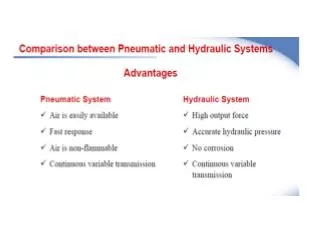
1. Ease and accuracy of control. Stopping Starting Speed control Position
2. Multiplication of force. A fluid power system can multiply forces simply and efficiently from a fraction of an ounce to several hundred tons of output.
3. Constant force or torque. - Only fluid power systems are capable of providing constant force or torque regardless of speed changes. • Instantly reversible motion - automatic protection against overloads - infinitely variable speed control. • the highest power-per-weight ratio of any known power source.
Drawbacks of Fluid Power Oil leakage from the hydraulic system into the surroundings. Hydraulic pipeline can burst due to excessive oil pressure if proper system design is not implemented In pneumatic systems, components such as compressed air tanks and accumulators must be properly selected to handle the system maximum air pressure. level of noise in the vicinity of fluid power systems.
Basic hydraulic system with Linear hydraulic actuator (cylinder).
There are six basic components required in a hydraulic system 1. A tank (reservoir) to hold the hydraulic oil 2. A pump to force the oil through the system 3. An electric motor or other power source to drive the pump 4. Valves to control oil direction, pressure, and flow rate 5. An actuator to convert the pressure of the oil into mechanical force or torque to do useful work. 6. Piping, which carries the oil from one location to another
There are six basic components required in Pneumatic System 1. An air tank to store a given volume of compressed air 2. A compressor to compress the air that comes directly from the atmosphere 3. An electric motor or other prime mover to drive the compressor 4. Valves to control air direction, pressure, and flow rate 5. Actuators, which are similar in operation to hydraulic actuators 6. Piping to carry the pressurized air from one location to another
Size and Scope - Over half of all U.S. industrial products have fluid power systems or components as part of their basic design. - About 75% of all fluid power sales are hydraulic and 25% are pneumatic.