Chapter 5 Peer-to-Peer Protocols and Data Link Layer
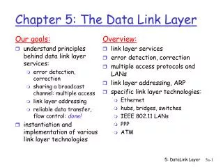
Chapter 5 Peer-to-Peer Protocols and Data Link Layer. PART II: Data Link Controls Framing Point-to-Point Protocol High-Level Data Link Control. Directly connected, wire-like Losses & errors, but no out-of-sequence frames Applications: Direct Links; LANs; Connections across WANs.

Chapter 5 Peer-to-Peer Protocols and Data Link Layer
E N D
Presentation Transcript
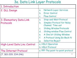
Chapter 5Peer-to-Peer Protocols and Data Link Layer PART II: Data Link Controls Framing Point-to-Point Protocol High-Level Data Link Control
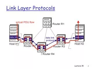
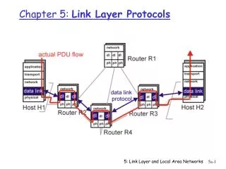
Directly connected, wire-like Losses & errors, but no out-of-sequence frames Applications: Direct Links; LANs; Connections across WANs Data Links Services Framing Error control Flow control Multiplexing Link Maintenance Security: Authentication & Encryption Examples PPP HDLC Ethernet LAN IEEE 802.11 (Wi Fi) LAN Packets Packets Data link layer Data link layer Frames A B Physical layer Physical layer Data Link Protocols
Mapping stream of physical layer bits into frames Mapping frames into bit stream Frame boundaries can be determined using: Character Counts Control Characters Flags CRC Checks received frames transmitted frames Framing 0111110101 0110110111 Framing
Data to be sent A DLE B ETX DLE STX E After stuffing and framing DLE STX A DLE DLE B ETX DLE DLE STX E DLE ETX Character-Oriented Framing • Frames consist of integer number of bytes • Asynchronous transmission systems using ASCII to transmit printable characters • Octets with HEX value <20 are nonprintable • Special 8-bit patterns used as control characters • STX (start of text) = 0x02; ETX (end of text) = 0x03; • Byte used to carry non-printable characters in frame • DLE (data link escape) = 0x10 • DLE STX (DLE ETX) used to indicate beginning (end) of frame • Insert extra DLE in front of occurrence of DLE STX (DLE ETX) in frame • All DLEs occur in pairs except at frame boundaries
HDLC frame any number of bits Flag FCS Control Information Flag Address Framing & Bit Stuffing • Frame delineated by flag character • HDLC uses bit stuffing to prevent occurrence of flag 01111110 inside the frame • Transmitter inserts extra 0 after each consecutive five 1s inside the frame • Receiver checks for five consecutive 1s • if next bit = 0, it is removed • if next two bits are 10, then flag is detected • If next two bits are 11, then frame has errors
Data to be sent (a) 0110111111111100 After stuffing and framing 0111111001101111101111100001111110 (b) Data received 01111110000111011111011111011001111110 After destuffing and deframing *000111011111-11111-110* Example: Bit stuffing & de-stuffing
Flag Address Flag Control Protocol Information CRC 01111110 01111110 1111111 00000011 integer # of bytes All stations are to accept the frame Specifies what kind of packet is contained in the payload, e.g., LCP, NCP, IP, OSI CLNP, IPX Unnumbered frame PPP Frame • PPP uses similar frame structure as HDLC, except • Protocol type field • Payload contains an integer number of bytes • PPP uses the same flag, but uses byte stuffing • Problems with PPP byte stuffing • Size of frame varies unpredictably due to byte insertion • Malicious users can inflate bandwidth by inserting 7D & 7E
Data to be sent 41 7D 42 7E 50 70 46 7E 41 7D 5D 42 7D 5E 50 70 46 7E After stuffing and framing Byte-Stuffing in PPP • PPP is character-oriented version of HDLC • Flag is 0x7E (01111110) • Control escape 0x7D (01111101) • Any occurrence of flag or control escape inside of frame is replaced with 0x7D followed by original octet XORed with 0x20 (00100000)
GFP payload area 2 0-60 2 2 2 PLI GEH cHEC Type tHEC GFP payload Payload type GFP extension headers Payload length indicator Core header error checking GFP payload Type header error checking Generic Framing Procedure • GFP combines frame length indication with CRC • PLI indicated length of frame, then simply count characters • cHEC (CRC-16) protects against errors in count field (single-bit error correction + error detection) • GFP designed to operate over octet-synchronous physical layers (e.g. SONET) • Frame-mapped mode for variable-length payloads: Ethernet • Transparent mode carries fixed-length payload: storage devices
GFP Synchronization & Scrambling • Synchronization in three-states • Hunt state: examine 4-bytes to see if CRC ok • If no, move forward by one-byte • If yes, move to pre-sync state • Pre-sync state: tentative PLI indicates next frame • If N successful frame detections, move to sync state • If no match, go to hunt state • Sync state: normal state • Validate PLI/cHEC, extract payload, go to next frame • Use single-error correction • Go to hunt state if non-correctable error • Scrambling • Payload is scrambled to prevent malicious users from inserting long strings of 0s which cause SONET equipment to lose bit clock synchronization (as discussed in line code section)
Chapter 5Peer-to-Peer Protocols and Data Link Layer Point-to-Point Protocol
PPP: Point-to-Point Protocol • Data link protocol for point-to-point lines in Internet • Router-router; dial-up to router 1. Provides Framing and Error Detection • Character-oriented HDLC-like frame structure 2. Link Control Protocol • Bringing up, testing, bringing down lines; negotiating options • Authentication: key capability in ISP access 3. A family of Network Control Protocols specific to different network layer protocols • IP, OSI network layer, IPX (Novell), Appletalk
PPP Applications PPP used in many point-to-point applications • Telephone Modem Links 30 kbps • Packet over SONET 600 Mbps to 10 Gbps • IP→PPP→SONET • PPP is also used over shared links such as Ethernet to provide LCP, NCP, and authentication features • PPP over Ethernet (RFC 2516) • Used over DSL
2 or 4 1 or 2 variable Address Flag Flag Control Protocol Information FCS 01111110 01111110 1111111 00000011 CRC 16 or CRC 32 All stations are to accept the frame HDLC Unnumbered frame PPP Frame Format • PPP can support multiple network protocols simultaneously • Specifies what kind of packet is contained in the payload • e.g. LCP, NCP, IP, OSI CLNP, IPX...
1. Carrier detected Dead 7. Carrier dropped Failed Establish Terminate 2. Options negotiated 6. Done Failed Authenticate 5. Open 3. Authentication completed 4. NCP configuration Network PPP Phases Home PC to Internet Service Provider 1. PC calls router via modem 2. PC and router exchange LCP packets to negotiate PPP parameters 3. Check on identities 4. NCP packets exchanged to configure the network layer, e.g. TCP/IP ( requires IP address assignment) 5. Data transport, e.g. send/receive IP packets 6. NCP used to tear down the network layer connection (free up IP address); LCP used to shut down data link layer connection 7. Modem hangs up
PPP Authentication • Password Authentication Protocol • Initiator must send ID & password • Authenticator replies with authentication success/fail • After several attempts, LCP closes link • Transmitted unencrypted, susceptible to eavesdropping • Challenge-Handshake Authentication Protocol (CHAP) • Initiator & authenticator share a secret key • Authenticator sends a challenge (random # & ID) • Initiator computes cryptographic checksum of random # & ID using the shared secret key • Authenticator also calculates cryptocgraphic checksum & compares to response • Authenticator can reissue challenge during session
Example: PPP connection setup in dialup modem to ISP LCP Setup PAP IP NCP setup
Chapter 5Peer-to-Peer Protocols and Data Link Layer High-Level Data Link Control
High-Level Data Link Control (HDLC) • Bit-oriented data link control • Derived from IBM Synchronous Data Link Control (SDLC) • Related to Link Access Procedure Balanced (LAPB) • LAPD in ISDN • LAPM in cellular telephone signaling
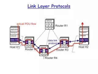
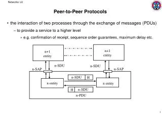
NLPDU Network layer Network layer “Packet” DLSAP DLSDU DLSDU DLSAP DLPDU Data link layer Data link layer “Frame” Physical layer Physical layer
Commands Primary Responses Secondary Secondary Secondary Commands Secondary Primary Responses Primary Secondary Commands Responses HDLC Data Transfer Modes • Normal Response Mode • Used in polling multidrop lines • Asynchronous Balanced Mode • Used in full-duplex point-to-point links • Mode is selected during connection establishment
Flag FCS Control Information Flag Address HDLC Frame Format • Control field gives HDLC its functionality • Codes in fields have specific meanings and uses • Flag: delineate frame boundaries • Address: identify secondary station (1 or more octets) • In ABM mode, a station can act as primary or secondary so address changes accordingly • Control: purpose & functions of frame (1 or 2 octets) • Information: contains user data; length not standardized, but implementations impose maximum • Frame Check Sequence: 16- or 32-bit CRC
Information Frame 1 2-4 5 6-8 N(R) 0 N(S) P/F Supervisory Frame 1 N(R) 0 S S P/F Unnumbered Frame 1 1 M M M M P/F M Control Field Format • S: Supervisory Function Bits • N(R): Receive Sequence Number • N(S): Send Sequence Number • M: Unnumbered Function Bits • P/F: Poll/final bit used in interaction between primary and secondary
Information frames • Each I-frame contains sequence number N(S) • Positive ACK piggybacked • N(R)=Sequence number of next frame expected acknowledges all frames up to and including N(R)-1 • 3 or 7 bit sequence numbering • Maximum window sizes 7 or 127 • Poll/Final Bit • NRM: Primary polls station by setting P=1; Secondary sets F=1 in last I-frame in response • Primaries and secondaries always interact via paired P/F bits
Error Detection & Loss Recovery • Frames lost due to loss-of-synch or receiver buffer overflow • Frames may undergo errors in transmission • CRCs detect errors and such frames are treated as lost • Recovery through ACKs, timeouts & retransmission • Sequence numbering to identify out-of-sequence & duplicate frames • HDLC provides for options that implement several ARQ methods
Supervisory frames Used for error (ACK, NAK) and flow control (Don’t Send): • Receive Ready (RR), SS=00 • ACKs frames up to N(R)-1 when piggyback not available • REJECT (REJ), SS=01 • Negative ACK indicating N(R) is first frame not received correctly. Transmitter must resend N(R) and later frames • Receive Not Ready (RNR), SS=10 • ACKs frame N(R)-1 & requests that no more I-frames be sent • Selective REJECT (SREJ), SS=11 • Negative ACK for N(R) requesting that N(R) be selectively retransmitted
Unnumbered Frames • Setting of Modes: • SABM: Set Asynchronous Balanced Mode • UA: acknowledges acceptance of mode setting commands • DISC: terminates logical link connectio • Information Transfer between stations • UI: Unnumbered information • Recovery used when normal error/flow control fails • FRMR: frame with correct FCS but impossible semantics • RSET: indicates sending station is resetting sequence numbers • XID: exchange station id and characteristics
Data transfer SABM UA UA DISC Connection Establishment & Release • Supervisory frames used to establish and release data link connection • In HDLC • Set Asynchronous Balanced Mode (SABM) • Disconnect (DISC) • Unnumbered Acknowledgment (UA)
Secondaries B, C Primary A B, RR, 0, P B, I, 0, 0 B, I, 1, 0 X B, I, 2, 0,F B, SREJ, 1 C, RR, 0, P C, RR, 0, F B, SREJ, 1,P B, I, 1, 0 B, I, 3, 0 B, I, 4, 0, F B, I, 0, 5 Time Example: HDLC using NRM (polling) Address of secondary N(S) N(R) A polls B B sends 3 info frames N(R) A rejects fr1 A polls C C nothing to send A polls B, requests selective retrans. fr1 B resends fr1 Then fr 3 & 4 A send info fr0 to B, ACKs up to 4
Combined Station B Combined Station A B, I, 0, 0 A, I, 0, 0 B, I, 1, 0 A, I, 1, 1 X A, I, 2, 1 B, I, 2, 1 B, I, 3, 2 B, REJ, 1 B, I, 4, 3 A, I, 3, 1 B, I, 1, 3 B, I, 2, 4 B, RR, 2 B, I, 3, 4 B, RR, 3 Frame Exchange using Asynchronous Balanced Mode A ACKs fr0 B sends 5 frames A rejects fr1 B goes back to 1 A ACKs fr1 A ACKs fr2
I3 I6 I4 RR6 I5 RNR5 Flow Control • Flow control is required to prevent transmitter from overrunning receiver buffers • Receiver can control flow by delaying acknowledgement messages • Receiver can also use supervisory frames to explicitly control transmitter • Receive Not Ready (RNR) & Receive Ready (RR)