The Surveyor
The Surveyor. By: Randy Direen, David Cox, Ali Abali, Leonardo Carrasco, Lisa Prince Preliminary Design Review January 25, 2005. Objectives & Purpose.

The Surveyor
E N D
Presentation Transcript
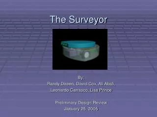
The Surveyor By: Randy Direen, David Cox, Ali Abali, Leonardo Carrasco, Lisa Prince Preliminary Design Review January 25, 2005
Objectives & Purpose The objective of our project is to build a mobile robot capable of mapping out its surroundings using ultrasonic vision and displaying this map on a computer display. The purpose of such a machine would be the first step in developing a robot that could intelligently “learn” its environment and use what it has learned to make decisions for navigation.
Base Objectives • Mobile unit using 2 motors driving 2 wheels • Map out immediate surroundings using ultrasonics • Display the map on laptop / computer • Based on the map make intelligent decision for navigation • Communicate w/ remote computer using RS-232 serial communication (possibly RF control) • 2 modes of control - autonomous and manual control for moving in places of interest
Components: Outline of Approach • Processor: microcontroller, microprocessor, • Sensor and Scanner: receivers, transmitter, oscillator, dual A/D, FPGA • Motors: stepper motors • Power: battery
Processor: Implementation • Microcontroller: • Motorola 68HC11 microcontroller • provides an internal serial interface. • Real time interrupt circuit. • Variable baud rates. • Transparent Latch • Latches the address of the lower 8 multiplexed address / data bits. • Flash ROM • contains the start up code for the microcontroller. • SRAM • contains the firmware required by peripheral devices controlled by the controller, and the program software.
Processor: Implementation • Microprocessor: • Motorola 68000 microprocessor • 32 bit registers for fast computations. • 24 bit address bus with capability of addressing up to 16 Mbytes of memory. • Flash ROM • contains the start up code for the microprocessor. • SRAM • contains the program software and data points for mapping. • FPGA: • Spartan 3 • Provide the memory mapping decode logic for the microcontroller. • LCD: • Alphanumeric LCD controller • Displays the distance received from the sensor unit.
Sensor & Scanner: Outline of Approach • Recievers: two of them on either side of the transmitter. For modularity they will be on their own separate boards—making testing easy. Before the signal is fed into the A/D it will be amplified and filtered. • Transmitter: also its own module for ease of testing. It will have a preamp before the transducer and a switch before that for modulating a pulse. • Oscillator: around 200KHz source for the modulated pulse, this will be fed into the transmitter. • Dual A/D: this device will sample both incoming signals simultaneously. • FPGA: to do signal processing on the two incoming signals (such as an autocorrelation).
Sensor & Scanner: Implementation • Reciever parts and Implementation • Narrow band ultrasonic transducers such as the E-188/215. • Low noise operational amplifiers. • Butterworth low pass filters. These receivers will be on separate boards which will eventually clip onto the scanner. Initially we will use wire wrapped boards for testing, however, we intend to put these on printed circuit boards in the future because of anticipated noise issues.
Sensor & Scanner: Implementation • Transmitter parts and Implementation • Narrow band ultrasonic transducers such as the E-188/215. • Low noise operational amplifiers. • MOSFET or other device for switching. Transmitter will also be on its own board for testing and eventually placed on a printed circuit board for reducing noise.
Sensor & Scanner: Implementation • Dual A/D • This will be for sampling the signals from the two receivers simultaneously. • FPGA • Spartan 3 This could also be the TI DSP if we can find the support.
Motors: Implementation • Stepper Motors • 2 stepper motors used for motion of the Surveyor • 2 controllers that will receive data from the microcontroller to manipulate the rotation of the motors. This in turn will control the direction of motion. The motors will be implemented on a 3 wheel base. The 2 motors control direction of motion and the 3rd wheel provides stability androtational freedom for the robot.
Power: Implementation • Power Source • 24 Volt Lithium battery. • Power converters to step down voltage to 3.3 V and 5 V levels. • 24 V supply required to drive the stepper motors. • Lithium battery allows for recharge ability. • A cooling fan for preventing overheating of the internal components.
Division of Responsibility • Processor, Firmware, and Software • Ali & Lisa • Sensors and Scanner • Randy & Leo • Motor and Power • David, Leo, & Lisa
Outside Resources To Be Utilized • Aaron Prince • Maintenance & Project Manager, Koppers Industries, Denver CO • Aaron is advising us on the Mechanical design of the Surveyor and the implementation of motors.
Risks • Parts availability may cause delays • Orders can take up to 4 weeks for delivery • Unforeseen failures • Burned parts, unavailable parts, non-practical design