Download
1 / 19
190 likes | 209 Views
Explore the structural layout, mechanical interface, and electrical aspects of the T-170M Telescope, including instrumentation compartments and thermal boundary conditions.

E N D
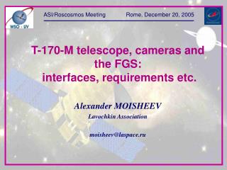
Interfaces of the Scientific Instrumentation, Telescope and Spacecraft SKRIPUNOVEVGENY Lavochkin Association skrip@laspace.ru
Presentation contents • Brief information about the T-170M Telescope • Structural layout of the Scientific Instrumentation Complex • Mechanical Interface 3.1. Layout of the Telescope Instrumental Compartment 3.2. Mechanical loadings 3.2. Structural materials and coatings 3.4. Cleanliness 4. Thermal boundary conditions 5. Weather environments 6. Electrical interface 6.1. Electrical power supply 6.2. Control 6.3. Data transmission
Brief information of the Telescope • Telescope mass – 1600 kg • Primary Mirror diameter – 1,7 m • F-ratio – 10 • Field of View, angular diameter – 30 arc.min • Accuracy of the light source image stabilization in the Focal Plane – 0,1arc.sec • Scientific Instrumentation Complex: - UVES; - VUVES; - LSS; - Imager unit. • Telescope average power consumption – 750 W • Average power consumption of the Scientific Instrumentation Complex – 300 W
T-170M Telescope Structural Layout Imager Control Unit
Mechanical interfaceLayout of the Telescope Instrumentation Compartment
Arrangement of the Scientific Instrumentation in the Telescope Instrumental Compartment Primary Mirror Unit Optical Bench Mounting Unit Imager Unit Optical Bench Guiding Sensor
Instrumentation mountings on the External Instrumentation Panel
Initial background for the Imager Unit development • The imagers are integrated into the single structure unit – Imager Unit; • The each Imager (except the central one) is equipped with mirror transferring the light flux to the Imager reception path; • The Imager Unit is mounted to the Optical Bench with three points; • Electronic Boxes of the Imager Unit are located outside of the Telescope (beyond the Telescope Instrumental Compartment) on the thermostabilized honeycomb panels; • The Electronic Boxes are produced as monoblocks
Mechanical loadings • Operational linear accelerations • Stiffness criteria • Stationary vibration environment (sinusoidal and random vibrations) • Shock impact • Acoustical environment The data is presented in Annex 1 for the Presentation
Structural materials and coatings Optical Bench material – aluminum alloy AL19 • Densitykg/m3 – 2780 • Thermal linear expansion factor 1/C - 19,510-6 • Elasticity modulus,E GPa – 70 • Breaking point, b MPa – 300 • Yield point, 02 MPa – 200 • Poisson’s ratio, - 0,3 Telescope Instrumental Compartment is provided with internal black antireflective coating - Coating emissivity 0,9
Cleanliness The cleanliness of gas medium of Telescope Instrumental Compartment no worse than class 8 of Russian Standard GOST8 ISO14644-1-2002 (no more than 3500 particles of size 0,5 m in 1 litre of air). The cleanliness is provided with continuous blowdown of the T-170M Telescope by gaseous nitrogen of dew point no worse than 5 C. At that the Telescope internal pressure should be provided at the level 0,003 MPa (0,03 kg/cm2). The Instrumentation should pass degassing in the Vacuum Chamber. The degassing mode: -temperature range +50 C …… +80C (to be precised). -pressure 1*10-4 …..1*10-5torr. -duration (total) – 10 days (to be precised).
Thermal boundary conditions • The Optical Bench operational temperature – plus 20C ±1C (to be precised). • Operational temperature of the Primary Mirror Unit - (minus 10..plus.20)С. • Average temperature of the mounting points of Optical Bench plus 20C . • Operational temperature of the insert and cover of Instrumental Compartment minus 10C …plus 20C. • Operational temperature of the External Instrumentation Panels intended for electronic boxes allocation – minus 20 Cplus 40 C. • The electronic boxes are wrapped with multilayer thermal insulation (MLI) : - specific thermal resistance – 35 К·m2/W; - absorptance of MLI external surface – AS = 0,4; - emissivity – ε = 0,6.
Weather environments Ground maintenance: Air temperature +18C …+25C. Short timetemperature +15C …+35C Relative humidity – up to 80% at temperature 20C. Storage: Air temperature +5C …+35C. Daily temperature difference no more than 10C. Air relative humidity 30% - 85% at temperature +20C. Total storage time at the short time temperature values up to +35C and relative humidity 98% no less than 3 days. Transportation: Temperature of gas medium inside the Telescope transportation container +5C …+35C and relative humidity no more than 30% at 20C (the ambient air temperature in range from minus 45Cup to +50C). At air transportation: - atmospheric pressure from 2∙104up to 1,05∙105Pa (from 150 up to 780 torr.); - pressure rate at the aircraft landing no more than 540 Pa/s (4 torr./sec).
Electrical interface Electric power supply • Power supply of the Scientific Instrumentation is provided from the direct current source at voltage (271,35)V at the output of Spacecraft Electric Power Supply System. • The circuit voltage drop should not exceed 1 V. • The Scientific Instrumentation should operate in a nominal mode at the voltage from 25V up to 29 V.
Electrical interface Control • The control is provided with pulse and digital commands, given by the Scientific Data Control Unit (SDCU). • The pulse command from SDCU are provided as the voltage pulses, given through two wires and having the following parameters: - amplitude minus 27 V +0 -2 Vconcerning the Bus "+27 V"; - duration(0,2...0,25)sec; - front time tf ≤100 microsec; - load current no more than 120 mA in every wire (from the two ones); - load capacitanceCl≤10 nanofarad. The digital commands are given by SDCU through the multiplex exchange channel, corresponding to the Standard MIL-STD-1553B.
Electrical interface Data transmitting • Scientific data transmission from the Scientific Instrumentation is performed through the interface MIL-STD-1553B. The data bit rate is about 800 kBps. • Telemetry data on the Scientific Instrumentation operation is transmitted as: - the digital array to the SDCU through the interface MIL-STD-1553B; - the signal parameters (on-line control date) to the Spacecraft Telemetry System.
The mass and power consumption constraints • * - including 20% reserve