Download
1 / 32
360 likes | 602 Views
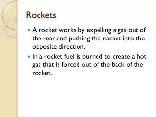
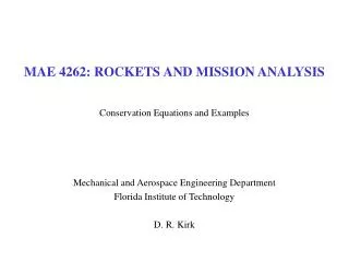
MAE 4262: ROCKETS AND MISSION ANALYSIS. Basics of Chemical Rocket Performance Mechanical and Aerospace Engineering Department Florida Institute of Technology D. R. Kirk. Schematic Diagram of a Conventional Liquid Rocket Motor (Figure 11.1 in Sforza). Northrop Grumman: LOX/LH2 Engine.

E N D
MAE 4262: ROCKETS AND MISSION ANALYSIS Basics of Chemical Rocket Performance Mechanical and Aerospace Engineering Department Florida Institute of Technology D. R. Kirk
Schematic Diagram of a Conventional Liquid Rocket Motor (Figure 11.1 in Sforza)
SUMMARY OF KEY EXIT VELOCITY, Ue, EQUATIONS • For high Ue (high Isp), desire • Propellants with low molecular weight, M • Propellant mixtures with large heat release, QR • High combustion chamber pressure, P02 NOTE: Sometimes subscript 2 is dropped, but still conditions in combustion chamber
SUMMARY OF KEY THRUST, T, EQUATIONS Comparison to best theoretical Measure from actual rocket (parameters that can be easily measured on a thrust stand)
OVERVIEW • Next page shows a plot of thrust ratio vs. area ratio • Figure compares two non-dimensional numbers • Abscissa is ratio of nozzle exit area to minimum area, or nozzle exit area to throat area (minimum area always occurs at throat), Ae/A* • Ordinate is ratio of thrust with diverging to converging nozzle, T/Tconv • Curve is plotted for constant ratio of specific heats, g = cp/cv = 1.2 • Curve would shift for g = 1.4 or any other value • Curves correspond to various ratios of Pa/P0 • Pa/P0 = ambient (atmospheric) to combustion chamber pressure • P0 is approximately constant for most rockets • Compare with Figure 11.7 (page 448) in Sforza
COMPARISON OF CONVERGING vs. DIVERGING NOZZLES • Examine ratio of thrusts, with and without a diverging section • Examine performance benefit of having diverging portion • Metric of comparison: • Excellent Web Site: http://www.engapplets.vt.edu/fluids/CDnozzle/cdinfo.html Chamber, Pa Chamber P0 Chamber P0 Converging Nozzle Converging-Diverging Nozzle
COMMENTS: CONVERGING NOZZLE (CTconv) • For nozzle with only a converging section → analysis is straightforward • Pa/P0 is varied in equation Evaluate at Me = 1 Sonic exit condition For converging nozzle Ae/A* = 1
THRUST COEFFICIENT, CTconv, FOR CONVERGING NOZZLES • Maximum Thrust Coefficient when Pa = 0 (expansion into a vacuum) • Ae/A*=1
COMMENTS: DIVERGING NOZZLE (CT) • Requires more analysis than simple converging nozzle • IMPORTANT POINT: We can not vary Pe/P0 and Ae/A* independently • Connected through Mach Number, Me Expression for Pe/P0 Vary Pa/P0 and Ae/A* Given A/A* → 2 Me Solutions Subsonic and Supersonic
MACH NUMBER vs. A/A* Differences in Cp/Cv Amplified as M ↑ For Given A/A* → 2 Solutions Subsonic and Supersonic Mach Highly Sensitive Region: Small Changes in A/A* → Large Changes in M
PERFORMANCE CHARACTERISTIC OF A 1-D ISENTROPIC NOZZLE WHAT DID WE DO HERE? • Set Pa/P0 = 0.05, g = 1.2 • For any Ae/A* determine supersonic Me • Using this Me calculate P0/Pe • Calculate CT • Plot CT/CTconv (or T/Tconv) as function of Ae/A* (which is equivalent to plotting CT as a function of Me (supersonic)) Function is Maximized when Pe = Pa
PERFORMANCE CHARACTERISTIC OF A 1-D ISENTROPIC NOZZLE Maximum Thrust (Pe = Pa) Diverging Portion Increases Thrust In terms of calculation, we could allow T/Tconv to become negative, but as we will soon see, we can deal with this part of the curve more realistically Diverging Portion Reduces Thrust
PERFORMANCE CHARACTERISTIC OF A 1-D ISENTROPIC NOZZLE Nozzle is Ideally Expanded Pe = Pa Curve can also tell us where Pe > or < Pa IF: Pe > Pa Nozzle is Under-Expanded IF: Pe < Pa Nozzle is Over-Expanded
PERFORMANCE CHARACTERISTIC OF A 1-D ISENTROPIC NOZZLE Nozzle is Ideally Expanded (Pe = Pa) Nozzle is Under-Expanded (Pe > Pa) Nozzle is Over-Expanded (Pe < Pa)
PERFORMANCE CHARACTERISTIC OF A 1-D ISENTROPIC NOZZLE Nominal Range of Pa/P0 Decreasing Back Pressure or Increasing Altitude
PERFORMANCE CHARACTERISTIC OF A 1-D ISENTROPIC NOZZLE Line of Maximum Thrust: Connects Locus of Maxima For each value of Pa/P0 there is an optimum area ratio for nozzle
PERFORMANCE CHARACTERISTIC OF A 1-D ISENTROPIC NOZZLE Small Ratios of Pa/P0 Require Very Large Area Ratios
EXAMPLE: ROCKET LAUNCH Ae/A* = 20 Burnout (Under-Expanded) ↑ Vertical Flight Max Thrust (Ideally Expanded) Launch (Over-Expanded) Notice we are closer to Optimum Thrust on Under-Expanded Side
PERFORMANCE CHARACTERISTIC OF A 1-D ISENTROPIC NOZZLE What can physically happen to supersonic flow in this region? For this combination of pressure ratios and area ratios, a shock enters nozzle
MODEL OF SHOCK IN EXIT PLANE • We can plot shock line by located a shock at exit plane of nozzle • Requires 1 additional equation • Flow across a normal shock to connect conditions • For a given g only one Pa/P0 for which a normal shock will locate in plane of a nozzle of given area ratio Ae/A*
PERFORMANCE CHARACTERISTIC OF A 1-D ISENTROPIC NOZZLE On this line a normal shock wave located at exit of nozzle
PERFORMANCE CHARACTERISTIC OF A 1-D ISENTROPIC NOZZLE If Pe reduced substantially below Pa flow can separate A rough approximation for this condition is: Pe/Pa < 0.4 NOTE: Axial thrust direction is not usually altered by separation and CT can actually be increased over non-separated case
THRUST COEFFICIENT PLOTS • Taken from: Rocket Propulsion Elements, 6th Edition, by G. P. Sutton • Notation • p1 = p0 • p2 = pe • p3 = pa • CF = CT • A2/At = e = Ae/A* • k = g = cp/cv • Comments: • Plots are only CF (CT), they are not normalized by CTconv as in Figure 11.3 • Large region of separated flow • Asymptotic behavior as p1/p3→ ∞ • pa/p0→ ∞ in H&P
KEY POINTS ON PERFORMANCE CURVE • How does a rocket flying vertically move on Performance Curve? • High Pa/P0 to Low Pa/P0 • P0 usually remains ~ constant during flight • Pa ↓ as altitude ↑ • As Pa/P0↓ very large Ae/A* for maximum thrust • How does optimal Ae/A* vary as rocket flies vertically? • Required Ae/A* for maximum thrust increases as rocket altitude increases • If T/Tconv < 1, diverging portion of rocket is hindrance • Actual rockets never operate in this region • Best nozzle gives best performance (Isp, range, etc.) over flight envelope • If nozzle operation is still unclear, lecture on operation of C-D nozzles coming soon
COMMENTS ON ACTUAL NOZZLES • Model of thermal rocket thrust chamber performance • Model has many simplifications → measure of best theoretical performance • Actual rockets benefit from diverging nozzle portion, operate above T/Tconv =1 • Actual thrust chambers (non-idealities important to consider) • Pressure losses associated with combustion process • Actual flow in nozzle is not isentropic • Friction • Heat losses • Shocks within nozzle • Chemistry • Frozen Flow: Propellant composition remains constant • Shifting Equilibrium: Composition changes with propellant temperature • Actual shape of nozzle affects performance
SUMMARY: WHAT HAVE WE DONE? • Simplified model of thermal rocket thrust chamber • Model resulted in connection between thermodynamics and exit velocity, Ue • Propellants with low molecular weight to achieve high exit velocity (high Isp) • Desirable to have propellant mixtures with large QR/M • Desirable to have high combustion chamber pressure, P0 • For a given thrust, higher P0 leads to lower A* (smaller rocket) • Increasing P0 leads to difficulties (stress, heat transfer, chemical issues) • Model resulted in connection between thermodynamics, geometry and exit velocity • Developed Characteristic Velocity, c*, and Thrust Coefficient, CT • Compare actual rockets to theoretical predictions • Developed plot of Performance Characteristics of a 1-D isentropic rocket nozzle BASICS OF THERMAL (CHEMICAL) ROCKET PROPULSION AND PERFORMANCE