Download
1 / 23
230 likes | 323 Views
Explore the assessment and advancements in diamond fabrication at the University of Connecticut, from uniform sample production to X-ray diffraction assessments and innovative laser ablation techniques.

E N D
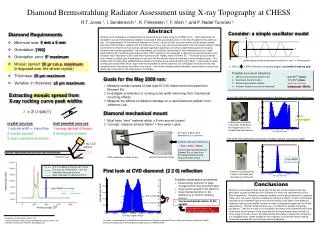
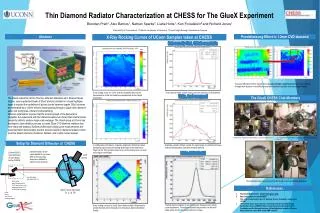
Diamond Radiator Fabrication and Assessment Brendan Pratt Fridah Mokaya Richard Jones University of Connecticut GlueX Collaboration Meeting, Jefferson Lab, October 2012
Outline • Assessment of uniform samples produced by VPIE • Advances with diamond ablation: improved optics • Images of UConn’s first “picture frame” diamond • Assessment of the UConn 40-micron sample • Plans for upcoming CHESS run Phase II STTR Project Interim Report, Sept., 2012 2 2
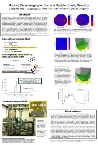
Uniform samples produced by VPIE raw material: type-3 CVD diamond from E6 original thickness ~150 microns 3 thinned samples: 150, 90, 30 microns thick surface and thickness profiles with Zygo X-ray rocking-curve topographs Phase II STTR Project Interim Report, Sept., 2012 3 3
sample 1: 150 microns thickness surface and thickness profiles (Zygo 3D) Phase II STTR Project Interim Report, Sept., 2012 4
sample 2: 90 microns thickness surface and thickness profiles (Zygo 3D) Phase II STTR Project Interim Report, Sept., 2012 5
sample 3: 30 microns thickness surface and thickness profiles (Zygo 3D) Phase II STTR Project Interim Report, Sept., 2012 6
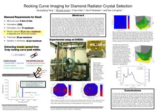
X-ray diffraction assessment – June 2012 • measurements at Cornell High Energy Synchrotron (CHESS)diffraction end-station C • special monochromator setup and diffractometer configured for these measurements • thanks to CHESS Staff Scientist Ken Finkelstein S150 – thick reference standard S90 – intermediate reference S30 – primary sample of interest Phase II STTR Project Interim Report, Sept., 2012
X-ray assessment: S150 surface of S150 was polished with RCMP process limited by instrumental resolution ! Phase II STTR Project Interim Report, Sept., 2012
X-ray assessment: S90 surface of S90 was not treated after VPIE process not as flat as S150, but still in spec. Phase II STTR Project Interim Report, Sept., 2012
X-ray assessment: S30 – the real target surface of S30 was not treated after VPIE process challenge lies here! Phase II STTR Project Interim Report, Sept., 2012
new idea tested in 2012: add a frame diamonds appear to warp severely when thinned to 20 microns try to stiffen the diamond by leaving a thick outer frame around the 20 micron region frame around 20 micron is still part of the single crystal, maintains planarity warping is from combination of mounting and internal stresses Phase II STTR Project Interim Report, Sept., 2012
First “picture frame” sample: U40 3 mm 300 micron frame around outside edge thinned inner rectangular window residual raster pattern is from a coarse laser step size Phase II STTR Project Interim Report, Sept., 2012 12 12
Diamond Laser Ablation at UConn UConn group has a pulsed excimer laser (193nm) that has been configured with optics for diamond machining. Laser operates at above ablation energies for hours of run time. Milling process has been automated for cutting predefined patterns in diamond (~30k pulses per fill) Beam spot has been “cleaned” of spherical aberrations. Milled trenches in Element6 3.2x3.2mm diamond Developed in-house ozone cleaning apparatus for removing amorphous carbon off milled diamond Phase II STTR Project Interim Report, Sept., 2012 13 13
3D Zygo Images of U40 White-light interferometer gives surface and thickness profiles with sub-micron prec. top surface measurements with Zygo approximate bottom surface depth, Zygo measurement on next slide Phase II STTR Project Interim Report, Sept., 2012 14 14
3D Zygo Images of U40 White-light interferometer gives surface and thickness profiles with sub-micron prec. average thickness 40μm Phase II STTR Project Interim Report, Sept., 2012 15 15
X-ray rocking curve for U40 surface of U40 was not treated after ablation excellent result for thinned diamond! Phase II STTR Project Interim Report, Sept., 2012 16 16
Observations on ablated sample Definition of the central region is good. Sharpness of the walls does not degrade with depth. Pileup of amorphous carbon is not catastrophic So far no clouding of the ablation chamber window from residue Excellent flatness of the central region So far no need for active correction to cutting rate, but pulse-by-pulse recording of laser power is being collected, can be used to keep the milling rate even more uniform Phase II STTR Project Interim Report, Sept., 2012 17 17
Upcoming CHESS Run CHESS recently acquired a new camera which will make scans 10x faster! Sinmat has just provided the first sample that has been picture-frame etched with a mask. U40 will soon become U20 Phase II STTR Project Interim Report, Sept., 2012 18 18
Questions? Phase II STTR Project Interim Report, Sept., 2012
Backup Slides Phase II STTR Project Interim Report, Sept., 2012
Improved laser optics First the laser beam is expanded setting L1 and L2’s focal points at the same location Finally, the light is focused through L3, a fused silica lens with a large radius of curvature (34.5mm) onto the target The “Point” is then imaged through L2, creating a parallel beam L1 L2 L3 Larger beam at L3 => more parallel beam at L3 => smaller focus at diamond Phase II STTR Project Interim Report, Sept., 2012 21 21
Improved Ablation Process: spread beam in y Top View beam spot out of laser is elliptical major axis is horizontal Beam spot spread widely in x Instead, tilt in y (required mechanical changes) Side View Beam spot now more symmetric Phase II STTR Project Interim Report, Sept., 2012 22 22
New vs. Old Spot Profile Wider spot size in y allows for larger step sizes and faster rasterizing. Aspect Ratio 1.5 Approx. 0.3mm Approx. 0.2mm Approx. 0.60mm after Approx. 0.15mm Aspect Ratio 4 before Phase II STTR Project Interim Report, Sept., 2012 23 23