Download
1 / 18
180 likes | 359 Views
Thin Diamond Radiator Fabrication for the GlueX Experiment. Brendan Pratt with Fridah Mokaya Richard Jones University of Connecticut. DNP 2012. Outline. Overview of GlueX UConn Laser Ablation Setup Analysis of Radiator Samples. DNP 2012. 2. 2. The GlueX Experiment. DNP 2012.

E N D
Thin Diamond Radiator Fabrication for the GlueX Experiment Brendan Pratt with Fridah Mokaya Richard Jones University of Connecticut DNP 2012
Outline • Overview of GlueX • UConn Laser Ablation Setup • Analysis of Radiator Samples DNP 2012 2 2
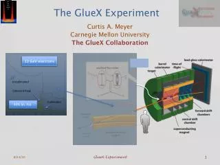
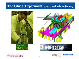
The GlueX Experiment DNP 2012
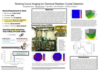
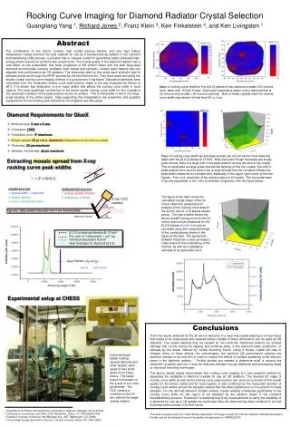
Thin and Flat Diamonds • Radiators restricted to 20μm thickness due to multiple scattering • Must also have well defined crystal structure with whole crystal rocking curves less than 35μr • Techniques for thinning diamond exist, but they leave samples stressed and “potato chipped” • Laser ablation as a viable method for machining while keeping internal crystal structure unchanged DNP 2012
UConn Laser Ablation Facility • CNC style XY translation and laser pulsing via LabView • Ablation Chamber optimized to reduce amorphous carbon deposition on windows • Enhanced optics to reduce spherical aberrations (sub micron beam spot) Ablation Chamber Diamond L3 L2 L1 LASER X-Y Translation Stage LabView DNP 2012
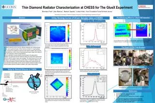
X-ray assessment: S150 surface of S150 was polished with RCMP process limited by instrumental resolution ! DNP 2012
X-ray assessment: S90 surface of S90 was not treated after VPIE process not as flat as S150, but still in spec. DNP 2012
X-ray assessment: S30 – the real target surface of S30 was not treated after VPIE process challenge lies here! DNP 2012
new idea tested in 2012: add a frame diamonds appear to warp severely when thinned to 20 microns try to stiffen the diamond by leaving a thick outer frame around the 20 micron region frame around 20 micron is still part of the single crystal, maintains planarity warping is from combination of mounting and internal stresses DNP 2012
First “picture frame” sample: U40 3 mm 315 micron frame around outside edge thinned inner rectangular window residual raster pattern is from a coarse laser step size DNP 2012 10 10
3D Zygo Images of U40 White-light interferometer gives surface and thickness profiles with sub-micron prec. top surface measurements with Zygo approximate bottom surface depth, Zygo measurement on next slide DNP 2012 11 11
3D Zygo Images of U40 White-light interferometer gives surface and thickness profiles with sub-micron prec. average thickness 40μm DNP 2012 12 12
X-ray rocking curve for U40 surface of U40 was not treated after ablation excellent result for thinned diamond! DNP 2012 13 13
Observations on ablated sample Central region looks good Sharpness of the walls does not degrade with depth Pileup of amorphous carbon is not catastrophic So far no clouding of the ablation chamber window from residue Excellent flatness of the central region So far no need for active correction to cutting rate, but pulse-by-pulse recording of laser power is being collected, can be used to keep the milling rate even more uniform Exploring annealing techniques DNP 2012 14 14
Questions? DNP 2012
Extra Slides DNP 2012
New vs. Old Spot Profile Wider spot size in y allows for larger step sizes and faster rasterizing. Aspect Ratio 1.5 Approx. 0.3mm Approx. 0.2mm Approx. 0.60mm after Approx. 0.15mm Aspect Ratio 4 before DNP 2012 17 17