Download
1 / 21
210 likes | 441 Views
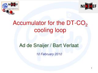
Accumulator for the DT-CO 2 cooling loop. Ad de Snaijer / Bart Verlaat 10 February 2010. DT Accumulator, Some numbers:. Volume Loop: 20.8 Liter Plant: 4.5 Liter Transfer and detector: 16.3 Liter Volume Accu: 32.7 Liter Total Filling: 23 kg Operational Level Range: 0 - 30%

E N D
Accumulator for the DT-CO2 cooling loop Ad de Snaijer / Bart Verlaat 10 February 2010
DT Accumulator, Some numbers: • Volume Loop: 20.8 Liter • Plant: 4.5 Liter • Transfer and detector: 16.3 Liter • Volume Accu: 32.7 Liter • Total Filling: 23 kg • Operational Level Range: 0 - 30% • Level at 40 bar(22ºC) standstill: 80% Chop LHCb-Velo Accumulator here and add 1m straight section • Capacity of heater and cooling spiral: 1kW, Cooling spiral does not grow with accumulator
PED Classification (1)(Pressure Equipment Directive) PED classification for CO2 DT-Accu. MDP = Relieve pressure > P@TenvMax x 110% PTP = 1.3 x MDP MDP = Maximum design pressure, PTP = Proof Test Pressure Class III: Pmax = 3000 bar*L / 32.7 Liter = 91.7 bar / 110% = 83 bar => 33.4ºC Components with non dangerous gasses P=83 bar 0.55 2.2 11.1 33.3 T=33.4ºC
PED Classification (2) Largest component determines the overall component category
How to continue... • The application is at the limit for class III. • We are studying the implications for PED • (Class III vs IV) • Do we really need a 32.7 Liter accumulator? • Or is the 20.7 liter for the loop realistic?
Design • Accumulator will be delivered in a support frame. • All terminals (Cooling, electrical) are on an outside patch panel. • Envelop issues: Current frame > 2.4m • Fixation to the floor? • Frame will be a closed black-box • All cold hardware insulated with 25mm Armaflex NH • Transport issues: • To wheel or not to wheel? • Lifting • How big is the door?
Electrical Interfaces: • 1 kW heater • 1 K-type thermocouple • 1 thermal switch (Clixon) • Pressure sensor (100 bar) (4-20mA) • Level measurement? • Capacitive (LHCb) • Load cell • Extra monitoring?
Pressure control with accumulator (1) Cooling spiral for pressure decrease (Condensation) Thermo siphon heater for pressure increase (Evaporation)
Pressure control with accumulator (2)PLC algorithm Upper limiter: Prevents overheating of heater due to dry-out. TT108 PT108 HT108 Set point Temperature VL003 TT101 Lower limiter: Limits accu cooling if pump subcooling is small
Technical specifications • We are preparing a specification document to freeze the requirements • We like to fill in the numbers during or after this meeting.
VTCS Accumulator Control 2PACL Start-up Cooling spiral for pressure decrease (Condensation) Pump head (Bar) Accumulator Pressure (Bar) Heater temp. (ºC) Accu Level (%) Decrease heater power near critical point to prevent dry-out Liquid temp. (ºC) Heater power (%) Pump inlet (ºC) • Accumulator Properties: • Volume 14.2 liter (Loop 9 Liter) • Heater capacity 1kW • Cooling capacity 1 kW Thermo siphon heater for pressure increase (Evaporation)
Accumulator Liquid level Over critical filling Under critical filling Loop fill ratio: 500 gram/liter Loop fill ratio: 575 gram/liter VTCS Design Loop fill ratio: 725 gram/liter Loop fill ratio: 650 gram/liter VTCS filling and sizing • Single-phase cold operation is worst-case for minimum level • (Heater need to be submerged all the time) • Two-phase cold operation is worst-case for maximum level • (Significant part of the cooling coil need to be in vapor phase) • Under critical fillings (<468 g/L) cause dry-out of accumulator near critical point. • Fillings just above critical density show best performance (500 – 600 g/L) • Ratio accumulator volume / loop volume: ±1.5 (AMS-TTCS & LHCb-VTCS)
bverlaat@nikhef.nl Valves • Good experience with Swagelok 43G ball valves. (2-way and 3-way) • -53ºC /172 bar • Nikhef has designed a handle extension for the 43G so warm panel mounting is possible. Ideal way of supporting the tubing structure. • 1 design for manual and automatic control • T-shape hole to avoid liquid trap • SS-43GHLVCR4 Electrical Control replaces manual knob
bverlaat@nikhef.nl CO2 pumps (1) Spring Damper • Good experience with the LEWA LDC1 metering pump in LHCb. • Modifications made for LHCb: • Spring loaded outlet valve (0.8 bar), normal for high viscous fluids • Heated oil bath to prevent moisture • (Toil=18ºC) • Dismountable isolation for easy access • LEWA pump gives pulsations • Gas damper • Gather gear pump under investigation for test plant • No pulsations • Smaller pump • First result: pumps well, but after 2 weeks in CO2 the gears got blocked due to swelling (PPP). New gear material under investigation. Isolation T=18ºC Q=130Watt Heater Lewa pump in LHCb
bverlaat@nikhef.nl Insulating • ¼” VCR (1/4” tube) and HVCR (3/8” tube) have connector diameter 19mm • Most other hardware is selected to match ~19mm. • Tubing is isolated to ø18mm • The rest is insulated with Armaflex NH 25-018 • Important: Air tight glued assembly to keep moisture out! Ø18 Ø68 Ø18