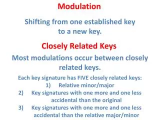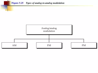
Analog Modulation
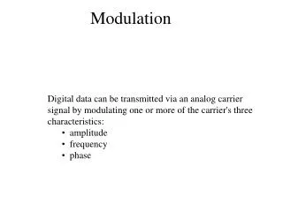
Analog Modulation. SSB – AM. W. U(f). SSB-AM. M(f). 2W. A. AAc 2 /2. f. f. -W 0 W. -f c. f c. USSB. USSB. LSSB. SSB – AM. Single Side Band Vs. Double Side Band Remove one side band from DSB USSB (Upper SSB) LSSB (Lower SSB). Hilbert transform of m(t) = m(t) (1/ t)

Analog Modulation
E N D
Presentation Transcript
Analog Modulation SSB – AM
W U(f) SSB-AM M(f) 2W A AAc2/2 f f -W 0 W -fc fc USSB USSB LSSB SSB – AM • Single Side Band Vs. Double Side Band • Remove one side band from DSB • USSB (Upper SSB) • LSSB (Lower SSB)
Hilbert transform of m(t) = m(t) (1/t) = m(t) h(t) F[H(m(t)] = M(f)H(f) -90 Phase shift h(t) = 1/t H(f) = -jsgn(f) m(t) SSB from complex envelope • Using complex envelope(analytic function) • USSB – AM • LSSB – AM
SSB in frequency domain • Take FT of z(t) • USSB • In bandpass
SSB in frequency domain • LSSB • In bandpass • Check the difference between text book and this result • Scale difference
M(f) Z(f) Ac in text 2Ac 1 f f -W W W U(f) Ac/2 in text Ac f -fc-W -fc fc fc+W Spectrum of USSB • Baseband Complex envelop • Spectrum of USSB
Sideband filter (Crystal filter) Bandpass filter Bandpass Filter for LSSB U(f) Local Oscillator f=fc Ac/2 f -fc-W -fc fc fc+W Generating SSB signal • Filter method • Most popular method • Excellent sideband suppression using crystal filter
-90 phase shift Local Oscillator f=fc -90 phase shift At f=fc Generating SSB signal • Phasing method • Using In-phase and Quadrature
BW, Power, SNR of SSB • BW of SSB is half the BW of DSB • BT = W • Power in SSB • Half of the power of DSB • Because One side band is removed • SNR of SSB • Same as DSB: • Both Power and Noise are half of DSB
Homework • Illustrative Problem 3.4 • Problems • 3.5, 3.6
Lowpass Filter SSB – AM demodulation • Coherent demodulation
U(f) Ac/2 f -fc-W -fc fc fc+W Lowpass Filter Y(f) Ac/4 f -W W -2fc-W -2fc 2fc 2fc+W SSB – AM demodulation • In frequency domain (USSB)
Lowpass Filter Effect of phase error on SSB – AM • Phase error in Local Oscillator • Attenuation by cos + Distortion by • If , will be demodulated instead of
Homework • Illustrative Problem 3.7 • Problems • 3.9, 3.12
VSB filter (Bandpass filter) Hv(f) uVSB(t) m(t) DSB Modulator uDSB(t) VSB – AM • VSB(Vestigial sideband) • Used in TV broadcasting • DSB takes too much BW (BT = 2W) for the TV channel • SSB is too expensive to implement • VSB is compromise between DSB and SSB • W BW 2W • Easy to implement receiver
UDSB(f) W f HVSB(f) f f UVSB(f) f VSB filter f -W -f f W -fc fc Spectrum of VSB – AM • VSB filter constraint is needed to undistorted recovery of m(t)