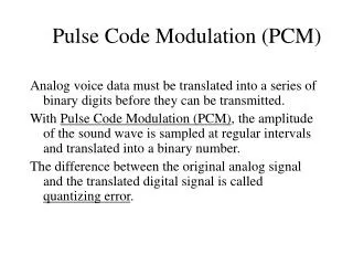
Download

1 / 33
340 likes | 625 Views
ICT–BVF–4.1 Lecture 6 Analog Modulation. Hassan Mesfer ICT-TE-7. TTC Riyadh, ICT–BS–1.2. 1. Modulation. Modulation is the process of modifying one of the parameters of a signal, called carrier, according to the message signal. Why use modulation: Ease of radiation

E N D
ICT–BVF–4.1 Lecture 6 Analog Modulation Hassan Mesfer ICT-TE-7 TTC Riyadh, ICT–BS–1.2 1
Modulation • Modulation is the process of modifying one of the parameters of a signal, called carrier, according to the message signal. • Why use modulation: • Ease of radiation • If we wish to throw a piece of paper (baseband signal), it cannot go too far by itself. • By wrapping it around a stone (carrier), it can be thrown over a longer distance • Simultaneous transmission of several signals • FDM (Frequency Division Multiplexing) uses analog modulation • TDM (Time Division Multiplexing) uses pulse modulation • Reduce noise and interference • Wideband noise reduction • For frequency assignment • Tune of radio or TV set to a particular station • Hardware design • To overcome hardware limitations • For certain range of frequencies is easier to design circuits 04/10/2014 TTC Riyadh, ICT–BVF–4.1 2
Modulation • There are different types of modulation: • Analog • Digital • Pulse modulation • Digital baseband modulation – line coding • Analog modulation • Message signal is analog • Carrier is a sinusoidal signal • Types of analog modulation: • AM (Amplitude Modulation), • FM (Frequency Modulation) • PM (Phase Modulation) 04/10/2014 TTC Riyadh, ICT–BVF–4.1 3
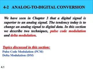
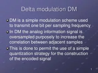
Modulation • Digital modulation • Message signal is digital • Carrier is a sinusoidal signal • Types of digital modulation: • ASK (Amplitude Shift Keying), Multilevel ASK • FSK (Frequency Shift Keying), MFSK • PSK Phase Shift Keying), QPSK, QAM • Pulse modulation • Message signal is analog • Carrier is a train of pulses • Types of digital modulation: • PAM (Pulse Amplitude Modulation) • PDF (Pulse Duration Modulation) or PWD (Pulse Width Modulation) • PPM (Pulse position Modulation) • PCM (Pulse Code Modulation), DPCM (Differential PCM) • DM (Delta Modulation), Adaptive DM 04/10/2014 TTC Riyadh, ICT–BVF–4.1 4
Analog Modulation • Analog modulation is the process of modifying one of the parameters of a sinusoidal signal, called carrier, according to variation in the amplitude of message signal. • The carrier signal has a higher frequency than the message signal. • The spectrum of the message signal is transferred into the higher-frequency band. • Demodulation is the process of extracting the message signal from the modulated signal. Modulated signal Message Message Modulator Demodulator Modulated signal Carrier Carrier 04/10/2014 TTC Riyadh, ICT–BVF-4.1 5
Types of Analog Modulation • By changing one of the parameters: amplitude, frequency, or phase of a sinusoidal carrier signal uc(t) = Uccos(2ft +) , • according to variation in the amplitude of message signal, the following analog modulation types are generated. • Amplitude - Amplitude modulation • Frequency - Frequency modulation • Phase - Phase Modulation Frequency Modulation (FM) Phase Modulation (PM) 04/10/2014 TTC Riyadh, ICT–BVF–4.1 6
Amplitude Modulation • The amplitude of the carrier signal is varied according to the message signal. • The frequency of the modulated signal remains same as the carrier frequency • Types of Amplitude Modulation • AM (Double Side Band with Carrier) • DSB-AM (Double Side Band Suppressed Carrier– DSBSC) • BW = 2W = 2 * BW of the message signal • SSB-AM(Single Side Band – AM) • BW = W • VSB-AM(Vestigial Side Band – AM) • BW = W ~ 2W • AM is also known as “Linear modulation” • Small bandwidth • Power inefficient • Applications • AM radio, TV video broadcasting(VSB), point-to-point communications (SSB), transmission of many telephone channels over microwave links 04/10/2014 TTC Riyadh, ICT–BVF–4.1 7
Amplitude Modulation Carrier signal Modulating signal Amplitude modulated signal 04/10/2014 TTC Riyadh, ICT–BVF–4.1 8
Modulating signal - Maximum amplitude of the modulating signal - Frequency of the modulating signal Carrier signal Amplitude modulated signal Amplitude Modulation 04/10/2014 TTC Riyadh, ICT–BVF–4.1 9
By rearranging the equation We get Take where is the modulation index. Amplitude modulated signal is: Modulation Index (Degree of Modulation) 04/10/2014 TTC Riyadh, ICT–BVF-4.1 10
The maximum occurs when (100% modulation) Once the modulation index is higher than 1 (i. e. ), over modulation. Modulation Index Phase reversal (a) (b) Figure : (a) 100% modulation. (b) Over modulation. 04/10/2014 TTC Riyadh, ICT–BVF-4.1 11
AM Frequency Spectrum & Bandwidth • Assume again that the modulating (message) signal is a cosinusoidal signal of frequency fm • Then, the amplitude modulated signal: • Consists of three components: • unmodulated carrier and two sidebands, located around the carrier frequency fc • upper sideband fc + fm and lower sidebandfc – fm. • the bandwidth of the amplitude modulated signal is 2fm 04/10/2014 TTC Riyadh, ICT–BVF-4.1 12
Efficiency of AM Signal • The efficiency of the amplitude modulated signal: • is given by: 04/10/2014 TTC Riyadh, ICT–BVF-4.1 13
Example of AM • The outputvoltageof a transmitterisgivenby 500(1 + 0.4 cos 3140t)cos 2π x105t. Calculate: • Carrierfrequency. • Modulatingfrequency. • Bandwidthofthemodulatedsignal. • Solution: On thewhitebord 04/10/2014 TTC Riyadh, ICT–BVF-4.1 14
Normally, the carrier does not convey any information. To increase the efficiency of amplitude modulation, the carrier can be suppressed. Therefore, the efficiency of AM can be increased up to 50%. However, the bandwidth of the DSB-SC remains same as amplitude modulated signal bandwidth (i.e. 2W). Double-Sideband Suppressed Carrier (DSB-SC) DSB-SC Signal 04/10/2014 TTC Riyadh, ICT–BVF-4.1 15
Using an analog multiplier chip (for low power applications in the labs) Generation of DSB-SC 04/10/2014 TTC Riyadh, ICT–BVF-4.1 16
Comparison – Different AM Schemes 04/10/2014 TTC Riyadh, ICT–BVF-4.1 17
Demodulation is the process of extracting the message signal from the modulated signal. Two types Multiplication detector (coherent detector) More complicated More expensive Envelope detection (Diode detection) Simple Cheaper AM Demodulation 04/10/2014 TTC Riyadh, ICT–BVF-4.1 18
To demodulate, the double sideband modulated signal is multiplied with the reference signal in time domain. As a reference signal a sinusoid with the same frequency and phase of the carrier signal is used. Coherent Demodulation LPF LPF (coherent carrier ) 04/10/2014 TTC Riyadh, ICT–BVF-4.1 19
No reference signal is needed. Once the amplitude modulated signal is passed through the diode (D), it is rectified by a half. The capacitor is used to remove the high frequency carrier in the positive detected half. Envelope Demodulation 04/10/2014 TTC Riyadh, ICT–BVF-4.1 20
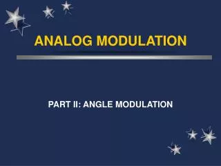
Non-linear modulation scheme. Either the phase or the frequency of the carrier signal is varied according to the message signal. The general form of angle modulated signal is Angle Modulation Frequency Modulation (FM) Angle Modulation Phase Modulation (PM) 04/10/2014 TTC Riyadh, ICT–BVF-4.1 21
The phase of the modulated signal is directly proportional to the modulating signal. Therefore, the phase modulated signal can be expressed as where is the peak phase deviation In PM modulation index μ is equal to: μ = K Am = ΔΦ Phase Modulation (PM) 04/10/2014 TTC Riyadh, ICT–BVF-4.1 22
Phase Modulation (PM) • For the phase modulated signal, maximum or minimum frequency deviations takes place near zero crossings of the modulating signal. Carrier signal Zero crossings Modulating signal Phase modulated signal
Demodulation of PM • In phase modulation the message is contained in the amount and rate of phase shift in a carrier wave. • Because of demodulation reasons, the frequency of m(t) is always kept much smaller than that of the carrier signal. • Main advantages of PM are improved signal to noise ratio and less radiated power 04/10/2014 TTC Riyadh, ICT–BVF-4.1 24
Frequency Modulation (FM) • In frequency modulation, the amplitude of the modulated carrier signal is kept constant while its frequency is varied by the modulating message signal. • The carrier frequencyis controlled at each instant by the voltage of the modulating signal. • The frequency of the modulated signal is increased if the input signal is positive, whereas the frequency is reduced if the input signal is negative. 04/10/2014 TTC Riyadh, ICT–BVF-4.1 25
For the frequency modulation, the phase of the modulated signal can be modified as Then, the frequency modulated signal is where is the peak frequency deviation. Modulation index in FM Frequency Modulation (FM) 04/10/2014 TTC Riyadh, ICT–BVF-4.1 26
Examples FM Example 1 For a given FM signal eFM(t) = 12cos(16 108 t + 5sin1250t) find the: • Carrier frequency • Modulating frequency • Modulation index • Maximum frequency deviation Example 2 The output voltage of a transmitter is given by 5cos (2π x108t + 25 sin 2π x103t). Calculate: • Carrier frequency. • Modulating frequency. • Frequency deviation Δf Example 3 Carrier with an amplitude of 5 V and a frequency of 100 MHz is frequency modulated (FM) by a cosinusoidal signal of 2 kHz. If frequency deviation is Δf = 75 kHz write the expression of the FM signal. 04/10/2014 TTC Riyadh, ICT–BVF-4.1 27
For FM, maximum or minimum frequency deviation takes place at negative or positive peaks of the modulating signal. Frequency Modulation (FM) Carrier signal Positive peak Modulating signal Negative peak Frequency modulated signal 04/10/2014 TTC Riyadh, ICT–BVF-4.1 28
Frequency Modulation Index β KfAm - frequency deviation fm – Modulated Signal Frequency Narrow Band Frequency Modulation (NBFM) • For small values of the frequency modulation index ( <<1), we have Narrow Band Frequency Modulation (NBFM). Frequency modulated signals are classified into two categories based on the value of modulation index • Wide Band Frequency Modulation (NBFM) • As the modulation index increases, the signal occupies more bandwidth. • In this case the modulation scheme is called Wide Band Frequency Modulation (WBFM). 04/10/2014 TTC Riyadh, ICT–BVF-4.1 29
Frequency Modulation Index 04/10/2014 TTC Riyadh, ICT–BVF-4.1 30
FM Demodulation • The frequency demodulator should produce an output voltage with instantaneous amplitude that is directly proportional to the instantaneous frequency of the input frequency modulated signal. • Thus, a frequency demodulator is a frequency-to-amplitude converter circuit • Various techniques are used to demodulate FM signal: • Slope detection • Zero-crossing detection • Phase locked discrimination • Quadrature detection 04/10/2014 TTC Riyadh, ICT–BVF-4.1 31
Comparison of AM and FM 04/10/2014 TTC Riyadh, ICT–BVF-4.1 32
Comparison of FM and PM 04/10/2014 TTC Riyadh, ICT–BVF– 4.1 33