Download

1 / 21
210 likes | 434 Views
Connecting VEX and ROBOTC Electrical Engineer Responsibilities. Electrical Engineer. Responsibilities: 1. Keep batteries charged 2. Work with Mechanical Engineer to attach the battery, motors and sensors to the model and the Cortex. 3. Work with the Computer Engineer to complete

E N D
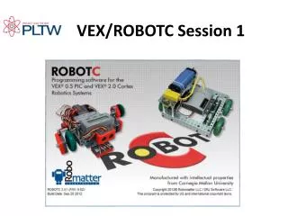
Connecting VEX and ROBOTCElectrical Engineer Responsibilities
Electrical Engineer Responsibilities: 1. Keep batteries charged 2. Work with Mechanical Engineer to attach the battery, motors and sensors to the model and the Cortex. 3. Work with the Computer Engineer to complete Motor and Sensor Setup 4. Complete the Motor and Sensor Schematic on Automation Through Programming Summary
Cortex • The VEX Cortex Microcontroller coordinates the flow of information and power on the robot. All electronic system components must interface to the Microcontroller. • The Microcontroller is the brain of every VEX robot.
Power • Keep batteries charged – In order for a robot to operate, it needs a power source. • A 7.2V NiCd rechargeable battery is used with your VEX robot. • Attach a battery strap to your model. • When your team is ready to test your model, retrieve a battery from the container of charged batteries. Attach the battery to the model using the strap and plug in to the Cortex. • At the end of class put your battery on the VEX charger so it will be ready for the next class.
Motors • 2. Attach Motors to the model and Cortex • Motors are devices that can transform electrical energy into mechanical energy. • They take electrical power and create rotary motion. Use motors to power the robot’s drive wheels. The wheels need to make continuous full rotations, which is exactly the kind of motion provided by the motors. Rotation for forward motion is shown.
Motors • 2-wire motors can be connected directly to ports 1 and 10 on the VEX Cortex • The VEX Motor Controller 29 allows you to connect the VEX 2-wire Motors to any of the standard 3-wire ports on the VEX Cortex. • To use the VEX Motor Controller 29, plug the 3-wire end into one of the MOTOR ports (2-9) on your VEX Cortex Microcontroller.
Motors • Connect the other end of the VEX Motor Controller to the 2-wire Motor. Be sure to align the black and red wires. • To prevent the 2-wire Motor and Motor Controller wires from accidentally separating while the robot is running, use the supplied wire ties to secure the two ends, along with any excess wire.
Claw • Notice the motor used to open and close the claw. • How many motors are needed for this project?
Sensors • 2. Attach Sensors to the model and Cortex • 4 Sensors: • Touch / • Bumper Switch • Limit Switch • Line Tracker • Potentiometer
Bumper Switch Sensor Signal: Digital Sensor Values: 1 = pressed, 0 = released Description: The bumper sensor is a physical switch. It tells the robot whether the bumper on the front of the sensor is being pushed in or not. Type: SPST switch (“Single Pole, Single Throw”) configured for Normally Open behavior. Signal Behavior:
Limit Switch Sensor Signal: Digital Sensor Values: 1 = pressed, 0 = released Description: The limit switch sensor is a physical switch. It can tell the robot whether the sensor’s metal arm is being pushed in or not. Type: SPDT microswitch, configured for SPST Normally Open behavior. Signal Behavior:
Line Tracker Signal: Analog Sensor Values: Range from 0-4095 Description: A line follower consists of an infrared light sensor and an infrared LED. It works by illuminating a surface with infrared light; the sensor then picks up the reflected radiation and, based on its intensity, determines the reflectivity of the surface. Light colored surfaces will reflect more light than dark surfaces. This allows the sensor to detect a dark line on a pale surface, or a pale line on a dark surface.
Line Tracker The line followers are an analog sensor, meaning that its output covers a range of values (in this case, from zero to five volts) rather than being only high (five volts) or low (zero volts), as is the case for a digital sensor. You can use the line trackers to help your robot navigate along a marked path. A typical application uses three line follower sensors, such that the middle sensor is over the line your robot is following.
Line Tracker You can use the line trackers to discern the boundary between two high-contrast surfaces as well. The optimal range for the line tracker to read a value is ¼ in. In this elevator model, the line tracker sensor is used to determine if the elevator is at the correct floor. Line Tracker Paper – ¼ in from sensor
Potentiometer Signal: Analog Sensor Values: Range from 0-4095 Description: The Potentiometer is used to measure the angular position of the axle or shaft passed through its center. The center of the sensor can rotate roughly 265 degrees and outputs values ranging from 0-4095 to the Vex Microcontroller. Mounted Potentiometer CAUTION! When mounting the Potentiometer on your robot, be sure that the range of motion of the rotating shaft does not exceed that of the sensor. Failure to do so may result in damage to your robot and the Potentiometer.
ROBOTC - Programming 3. Work with the Computer Engineer to complete Motor and Sensor Setup Allows you to configure and name all of the motors and sensors connected to your robot.
Motor and Sensor Setup Type a name to describe the motor location. Remember Ports 1 and 10 can be used for 2 – wire motors, or use a Motor Controller 29 to plug into ports 2-9. Check reversed if you want the motor to turn in the opposite direction.
Motor and Sensor Setup Type a name to describe the sensor. Choose the type of sensor – the only analog sensors for GTT are Line Follower and Potentiometer.
Motor and Sensor Setup Type a name to describe the digital sensor location or purpose. Both the limit and bumper switches are Touch Type. LED’s can be plugged in to Digital Ports 1-12, the type is VEX LED.
Motor and Sensor Schematic 4. Complete the Motor and Sensor Schematic on Automation Through Programming Summary This information should match the motor and sensors setup done in ROBOTC
Resources Carnegie Mellon Robotics Academy (2011). VEX Cortex Video Trainer. Retrieved from http://www.education.rec.ri.cmu.edu/products/teaching_robotc_cortex/index.html VEX Cortex Video Trainer • http://www.education.rec.ri.cmu.edu/products/teaching_robotc_cortex/index.html