
Engineering Geometry
E N D
Presentation Transcript
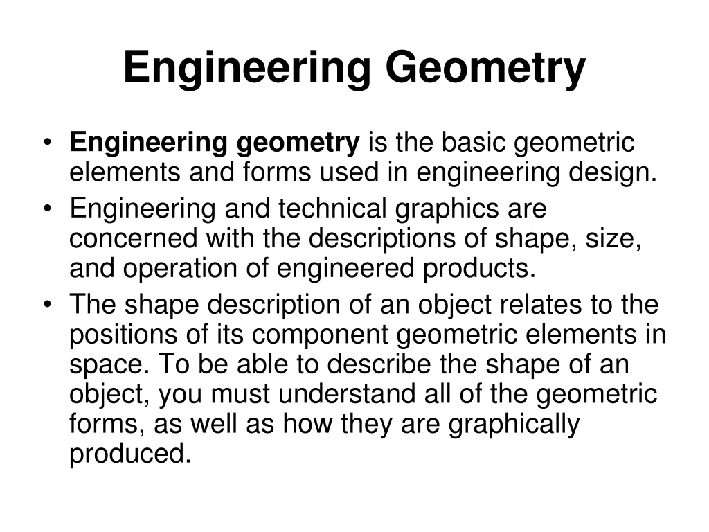
Engineering Geometry • Engineering geometry is the basic geometric elements and forms used in engineering design. • Engineering and technical graphics are concerned with the descriptions of shape, size, and operation of engineered products. • The shape description of an object relates to the positions of its component geometric elements in space. To be able to describe the shape of an object, you must understand all of the geometric forms, as well as how they are graphically produced.
Coordinate Space • 2-D Space: • Cartesian coordinatesystem: • A 2-D coordinate system establishes an origin at the intersection of two mutually perpendicular axes, labeled X (horizontal) and Y (vertical). • The origin is assigned the coordinate values of 0,0. • X: positive to the right of the origin, and negative to the left. • Y: positive above the origin, and negative below • Polar coordinate system: • Distance from the origin (0,0), and angle measured from the positive X-axis. • Distance is always positive. • Counterclockwise angle is positive; clockwise is negative.
3-D Coordinate Space • Cartesian coordinate system • Three mutually perpendicular axes (X, Y, and Z) intersect at the origin (0,0,0) • The right-hand rule is used to determine the positive direction of the axes. • A rectangular prism is created using the 3-D coordinate system by establishing coordinate values for each corner. • Cylindrical coordinates • locate a point on the surface of a cylinder by specifying a distance and an angle in the X-Y plane, and the distance in the Z direction. • Spherical coordinates • locate a point on the surface of a sphere by specifying an angle in one plane, an angle in another plane, and one height. • Absolute coordinates vs. Relative coordinates • World coordinate system vs. Local coordinate system
Geometric Elements • Point, Line, Circle, Arc • Parallel lines, perpendicular lines, intersecting lines • Tangent line • Curved lines: single curved vs. double curved • Circle: points equidistant from one point (the center) • circumference, radius, chord, diameter, secant, semicircle, arc, sector, quadrant, segment, tangent, concentric circles
Geometric Elements • Conic sections: formed by intersection of a plane with a right circular cone • Parabola: set of points equidistant from a fixed point (focus), and a fixed line (directrix) • Hyperbola: set of points whose distances from two fixed points (foci) have a common difference • Ellipse: set of points whose distances from two fixed points (foci) have a constant sum • Polygons and Polyhedrons; prisms and pyramids
Design Visualization • A dynamic process between the mind, the eyes, and some physical stimulus such as a drawing or an object.
Solid Object Features • Edges – lines that represent the boundary between two faces of an object. • Faces – areas of uniform or gradually changing lightness and are always bounded by edges. • Limiting element – a line that represents the farthest outside feature of a curved surface. • Vertex – point where more than two edges meet.
Visualization Techniques • Solid Object Combinations and Negative Solids • Cutting Planes • Normal • Rotated about single axis – inclined face • Rotated about two axes – oblique face • Planes of Symmetry • Developments – flattened “skin” of object
Additive and subtractive techniques can be used to make a solid geometric form