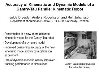
Download
1 / 37
380 likes | 600 Views
Robot Modeling and the Forward Kinematic Solution. ME 4135 Lecture Series 4 Dr. R. Lindeke – Fall 2011. Looking Closely at the 0 T n Matrix – the backbone of Robot Modeling. We define 0 T n as the matrix that relates the end of the arm frame to its base –

E N D
Robot Modeling and the Forward Kinematic Solution ME 4135 Lecture Series 4 Dr. R. Lindeke – Fall 2011
Looking Closely at the 0Tn Matrix – the backbone of Robot Modeling • We define 0Tn as the matrix that relates the end of the arm frame to its base – • Thus it must contain information related to each of the several joints of the robot • It is a 4x4 matrix populated by complex equations for both position and orientation (POSE)
Looking Closely at the 0TnMatrix • To get at the equation set, we will choose to add a series of coordinate frames to each of the joint positions • The frame attached to the 1st joint is labeled 0 while joint two has Frame 1, etc. • The last Frame is the end or n Frame Thus each individual “Transform” related two frames at each end of any link – That is Distal Motion in Proximal “Space”
Looking Closely at the 0TnMatrix • As we have seen earlier, we can define a HTM ( i-1Ti) to the transformation between any two SO3 based frames • Thus we will find that the 0Tnis given by a product formed by:
Looking Closely at the 0TnMatrix • For simplicity, we will redefine each of the of these transforms ( i-1Ti) as Ai • Then, for a typical 3 DOF robot Arm, 0Tn = A1*A2*A3 • While for a full functioned 6 DOF robot (arm and wrist) would be:0Tn= A1*A2*A3*A4*A5*A6 • A1to A3 ‘explain’ the arm joint effect while A4 to A6 explain the wrist joint effects
Looking At The Frame To Frame Arrangements – Building A Modeling Basis • When we move from one frame to another, we will encounter: • Two translations (in a controlled sense) • Two rotations (also in a controlled sense) • A rotation and translation WRT the Zi-1 • These are called the Joint Parameters • A rotation and translation WRT the Xi • These are called the Link Parameters
A model of the Joint Parameters NOTE!!!
Talking Specifics: • i is an angle measured about the Zi-1 axis from Xi-1 to Xi and is a variable for a revolute joint – fixed for a Prismatic Joint • diis a distance measured from the origin of Frame(i-1) to the intersection of Zi-1 and Xi and is a variable for a prismatic joint – fixed for a Revolute Joint
Talking Specifics -- cont • lior aiis the Link length and measures the distance from the intersection of Zi-1 to the origin of Framei measured along Xi • i is the Twist angle which measures the angle from Zi-1 to Zi as measured about Xi • Both of these parameters are fixed in value regardless of the joint type. • Further note: Fixed does not mean zero degrees or zero length just that they don’t change
Very Important to note: • Two Design Axioms prevail in this modeling approach • Axiom DH1: The Axis Xi must be designed to be perpendicular to Zi-1 • Axiom DH2: The Axis Xi must be designed to intersect Zi-1 • Oh, so within reason we can design the coordinate frames (they are under our control!)
Returning to the 4 Frame parameters • 1st is which is an operation of pure rotation about Z or: • 2nd is d which is a translation along Z or:
Returning to the 4 Frame parameters • 3rd is a Translation Along X or: • 4th is which is a pure rotation about X or:
So, Since We Can Control the Building of this Set Of Frames, What Are The Rules? • We will employ a method called the Denavit-Hartenberg Method • It is a Step-by-Step approach for modeling each of the frames from the initial or 0 frame all the way to the n frame • This modeling technique makes each joint axis (either rotation or extension) the Z-axis of the appropriate frame (Z0 to Zn-1). • The Joint motion is taken WRT the Zi-1 axis of the frame pair making up the transformation matrix
The D-H Modeling Rules: • Locate & Label the Joint Axes: Z0 to Zn-1 • Establish the Base Frame. Set Base Origin anywhere on the Z0 axis. Choose X0 and Y0 conveniently and to form a right hand frame.Repeat Steps 3 to 5 for i= 1 through n-1: • Locate the origin Oi where the common normal to Zi-1 and Zi intersects Zi. If Zi intersects Zi-1 locate Oi at this intersection. If Zi-1 and Zi are parallel, locate Oi at Joint i+1
The D-H Modeling Rules: • Establish Xi along the common normal between Zi-1 and ZithroughOi, or in the direction Normal to the plane Zi-1 – Zi if these axes intersect • Establish Yi to form a right hand system • Establish the End-Effector (n) frame: OnXnYnZn. Assuming the n-th joint is revolute, set kn = a along the direction Zn-1. Establish the origin On conveniently along Zn, at center of gripper or tool tip. Set jn = o in the direction of gripper closure (opening) and set in = n such that n=o x a (A vector cross product.) Note if tool is not a simple gripper, set Xn and Yn conveniently to form a right hand frame.
The D-H Modeling Rules: • Create a table of “Link” parameters: • i as angle about Zi-1 between X’s • di as distance along Zi-1 • i as angle about Xi between Z’s • lias distance along Xi • Form HTM matrices A1, A2, … An by substituting , d, and l into the general model • Form 0Tn= A1*A2*…*An
Some Issues to remember: • If you have parallel Z axes, the X axis of the second frame runs perpendicularly between them • When working on a revolute joint, the model will be simpler if the two X directions are in alignment at “Kinematic Home” • To achieve this kinematic home, rotate the model about moveable axes to align X’s • Kinematic Home is not too critical for prismatic joints • An ideal model will have n+1 frames • However, additional frames may be necessary – these are considered ‘Dummy’ frames since they won’t contain joint Z axes
Applying D-H to a General Case: Case 1: Like a part of a biological arm Case 2: Like a part of a R-P manipulator
General Case: Considering Joint I in “Case 1” • Connects Frames: i-1 and i • We Build The L.P. (link parameter) Table
An Example from MathCad And so on for each of the 5 Ai’s – which we will report using typical robot short hand on the next slide!
Solving for FKS • Here we have a special case – two of the Joints are a “planer arm” revolute set • These are contained in the A2 and A3 Matrices • These should be pre-multiplied using a trigonometric tool that recognizes any sum of angle cases • Basically: T0n = A1*{A2A3}*A4*A5
These 5 A Matrices will be developed into the Forward Kinematic Solution • Step 1: Build and Simplify A2*A3 the Simplified Product of these A2 and A3 Matrices: (This result is the "Parallel Arm" portion of the machine)
Continuing Then: • The FKS then is formed by "Pre-Multiplying" this parallel arm part by A1 (building the Arm solution) and then "Post-Multiplying" by the 'wrist' matrices A4*A5 Which Leads to a rather large and “Un-handy” Matrix that is best simplified and displayed in a Table!
FKS (in Robot Short Hand and extracted & Simplified from MathCad)
Finalizing the FKS – perform a physical verification • Physical verification means to plug known angles into the variables and compute the Ai’s and FKS against the Frame Skeleton • Easily done in MathCad, by giving angular values to each of i’s (1,2,3 & 5) of Zero radians or degrees and 0 units to d4 • And then Recopying 0T5 and simplifying mathematically