Download
1 / 40
420 likes | 735 Views
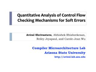
Quantitative Evaluation of Control Flow based Soft Error Protection Mechanisms. Abhishek Rhisheekesan. Compiler Microarchitecture Lab , Arizona State University, Tempe, Arizona, USA. Presentation overview. Problem: Control flow checking – a myth or necessity?

E N D
Quantitative Evaluation ofControl Flow basedSoft Error Protection Mechanisms Abhishek Rhisheekesan Compiler Microarchitecture Lab, Arizona State University, Tempe, Arizona, USA
Presentation overview • Problem: • Control flow checking – a myth or necessity? • No efficient and systematic methodology to evaluate soft error protection. • Solution: • An efficient and comprehensive framework for quantitative evaluation of system level protection. • Revelations: • Control flow checking is ineffective. • Decrease the overall reliability of the system by 0 – 21% • Performance overhead is 3.5 – 38%.
Importance of Soft Errors Fiscal Losses and Reactions • 2000 Sun Microsystems - Sun’s flagship servers suddenly crash! • Cosmic ray strikes on L2 cache • Verisign moved to IBM Unix servers • Fujitsu SPARC in 130 nm technology [1] • 80% of 200k latches protected with parity Ando et al., DAC 2003 • What is a soft error? • It is a bit flip in a circuit caused by a particle strike • Transient faults • Sources • Alpha particles • High energy neutrons • Output error, System crash • Increasing soft error rates • Reducing features sizes and lower supply voltage • More number of transistors per chip • Increasing clock rates
Types of Soft Error Protection Mechanisms • Control Flow Checking • EDDI - Error Detection by Duplicated Instructions • SEDSR – Soft Error Detection using Software Redundancy • REESE – REdundant Execution using Space Elements • DMR - Dual Modular Redundancy, TMR – Triple Modular Redundancy • Reunion, UnSync • EDDI - Error Detection by Duplicated Instructions [1] Instr1 Duplicate Instr1 Instr2 Duplicate Instr2 Cmp Result1, Result2 JNE Error Add R3, R1, R2 Add R33, R11, R22 Sub R5, R4, R3 Sub R55, R44, R33 Cmp R5, R55 JNE Error Oh et al., Transactions on Reliability 2002 Redundancy
What is Control Flow Checking? BB1 BB1 • Control Flow Checking Expected RSR = SIG1 • Transform RSR to SIG2 • CMP RSR, SIG2 • JNE ERROR • Instr1 • Instr2 • Instr3 • JMP BB3 1004 1008 100C 1010 1014 1018 101C Legal branch 1010 SIG2 Control Flow Error BB2 BB2 Legal branch Expected RSR = SIG2 • Transform RSR to SIG3 • CMP RSR, SIG3 • JNE ERROR • Instr5 • Instr6 • JMP BB4 2000 2004 2008 200C 2010 2014 • Software BB3 SIG3 BB3 Legal branch Expected RSR = SIG3 2010 BB4 BB4 • CFCSS - Control Flow Checking by Software Signatures [1] • Oh et al., Transactions on Reliability 2002
Why Control Flow Checking? Ohlsson et al., FTCS 1992. Schuette et al., Trans. Comput. 1987. • Early Fault Injection Results • RISC processors • Soft errors → control flow errors – 33% [1] • CISC processors • Soft errors → control flow errors – 77% [2] • Comparable error coverage to redundancy • <100% Performance overhead • Redundancy >100% Performance overhead • Conclusion of previous research: Control Flow Checking is a low overhead technique that has the potential to provide 33-77% error coverage.
Many Control Flow Checking Techniques • Control Flow Checking • Hardware • Hybrid • Software time 1980 1995 2006 • ASIS – Asynchronous Signatured Instruction Streams • W-D-P – Watchdog Direct Processing • OSLC – Online Signature Learning and Checking • CFCET - Control Flow Checking using Execution Tracing
Many Control Flow Checking Techniques • Control Flow Checking • Hardware • Hybrid • Software time 1982 1999 2008 1980 1995 2004 2006 • SIS – Signatured Instruction Streams • CSM – Continuous Signature Monitoring • WA & EPC – Watchdog Assists and Extended Precision Checksums • CFEDC – Control Flow Error Detection and Correction
Many Control Flow Checking Techniques • Control Flow Checking • Hardware • Hybrid • Software time 1982 1999 2008 1980 1995 2004 2006 2012 • CEDA - Control-Flow Error Detection Using Assertions • ACCE - Automatic Correction of Control-flow Errors • CFCSS - Control Flow Checking by Software Signatures • ECCA - Enhanced Control-Flow Checking Using Assertions • YACCA - Yet Another Control-Flow Checking using Assertions
Our analysis : CFC is ineffective • Originally reported overall error coverage was >90% • Our analysis results show CFC is ineffective. • System reliability is supposed to increase • But it reduces or doesn’t change • Performance loss on top of it
Problem : Evaluation methodology • Why targeted fault injection?
Challenge of Fault Injection Error free o/p Processor Pipeline Register File Identify Failures Application Binary Output Cache (Instruction/ Data) • Extremely Time Consuming • 32-bit register • Avg MiBench execution time • 39 billion cycles • Avg MiBench host simulation time • 1121s • Total fault injection runs required • 1.25 trillion • Total host simulation time required • 1399 trillion seconds = 252 years on 22 node cluster, each node with Dual Quad-Core Xeon processors Buffers Random faults injected on sequential elements Failure Rate = • Targeted fault injection is done because fault injection is practically infeasible
Problem in targeted fault injection • Targeted fault injection on branch instructions • E.g. Modify branch opcode to non-branch opcode • Instead of taking the branch, it will fall through • Good for verifying the working of the CFC technique • Control Flow Errors • Are not the only soft errors • Can happen due to indirect errors • Targeted fault injection is not sufficient for evaluating the protection provided to the system
Alternative : Vulnerability Processor Pipeline Register File ? Application Binary Output Output Cache (Instruction/ Data) Buffers W R W R R R Vulnerability: For 1 bit, it is the sum of the intervals during which it is used (Write to last Read). For a component (like a register), it is the sum of all such vulnerability intervals for all its bits. For a processor, it is the sum of all such bit-intervals for all its components. Register time V V NV Mukherjee et al., MICRO 2003
Alternative : Vulnerability Need a publicly available and validated Vulnerability Estimation Tool that models vulnerability of all processor components, and the protection achieved by CFC techniques • Mukherjee et al., MICRO 2003 • Biswas et al., ISCA 2005 • Fu et al., WMBS 2006 • Cheng et al, J. Cent. South Univ 2012
Contributions Mukherjee et al., MICRO 2003 • Develop and validate a simulation-based vulnerability estimation tool • Based on vulnerability definitions from AVF [1] • Validated using fault injection • Main Contribution: Systematic methodology for evaluating the protection of CFC techniques
GemV*: Simulation-based Vulnerability Measurement GemV Pipeline Buffers VT VT Pipeline registers O3 CPU RF VT Cache VT W R W R R R Register Output Vulnerability time V V NV • Calculating vulnerability • Vulnerability Tracker (VT) in each module • Model vulnerability of all sequential processor components • L1 Data/Instruction Caches, WB, DTLB, ITLB, RF, Rename Table, Pipeline registers, IQ, ROB, LSQ. • *Based on gem5 • V is for Vulnerability
Pipeline Vulnerability Modeling Vulnerable bits per instruction per pipeline stage Obtained from ARM AMBER RTL Validated using fault injection in RTL Currently available vulnerability estimation tools don’t model pipeline vulnerability accurately.
Contributions Mukherjee et al., MICRO 2003 • Develop and validate a simulation-based vulnerability estimation tool • Based on vulnerability definitions from AVF [1] • Validated using fault injection • Main Contribution: Systematic methodology for evaluating the protection of CFC techniques
Control Flow Error PC Caches(Dcache, Icache, Dtag, Itag, DTLB, ITLB) PC NPC PC RF Pipeline Registers Pipeline Buffers (IQ, ROB, LSQ, BTB, Rename table) t t +1 i i correct incorrect k j cycle • A control flow error causes a deviation from expected sequence of execution. • This means a deviation from • An expected PC transition from i at cycle t to j at cycle t+1. • Instead, an erroneous PC value of k is loaded at cycle t+1.
Protection Model: Fault to Error A bit flip in a bit at cycle t 2 How to identify if a bit flip translates to a modified NPC and, what is that PC → modified NPC? Identify the set of PC → modified NPC. Let the set cardinality be n. How to identify if a PC → NPC is in the safe zone or vulnerable zone? Initialize i = 0 1 yes Is the set element PC → NPCi in the vulnerable zone (or safe zone)? no i < n? i++ no yes Bit is not vulnerable Bit is vulnerable
Is PC NPC in the safe zonefor CFCSS? Expected RSR = SIG1 • Transform RSR to SIG2 • CMP RSR, SIG2 • JNE ERROR • Instr1 • Instr2 • Instr3 • JMP BB3 1004 1008 100C 1010 1014 1018 101C Jump to same BB : NOT DETECTED 1010 1010 SIG2 BB2 1018 Jump to different BB : DETECTED Expected RSR = SIG2 • Transform RSR to SIG3 • CMP RSR, SIG3 • JNE ERROR • Instr5 • Instr6 • JMP BB4 2000 2004 2008 200C 2010 2014 SIG3 BB3 2010 PC → NPC category Expected RSR = SIG3
Mapping table for CFCSS • How to identify if a PC → NPC is in the safe zone or vulnerable zone? PC → NPC value Mapping table from PC → NPC category to SZ or VZ Identify PC → NPC category Is it in safe zone or vulnerable zone? Vulnerable Zone Safe Zone O – Original Source Code C – CFC Code OS – Original Same BB OD – Original Different BB CL – CFC legal target CA – CFC aliased target CO – CFC other than LA
Fault to Error : PC IF/ID ID/EX EX/MEM MEM/WB PC PC Branch Target Addr PC Adder Opcode BO BO Shift Left 2 Instruction Cache Decode logic Br Br MUX Adder 4 How to identify a bit flip translates to a PC → modified NPC, and what is that PC → NPC?
Fault to Error : PC IF/ID ID/EX EX/MEM MEM/WB PC PC Branch Target Addr PC Adder Opcode BO BO Shift Left 2 Instruction Cache Decode logic Br Br MUX Adder 4 PC = Current PC NPC = (1-bit hamming distance PC) + 4
Fault to Error : Pipeline registers IF/ID ID/EX EX/MEM MEM/WB PC PC Branch Target Addr PC Adder Opcode BO BO Shift Left 2 Instruction Cache Decode logic Br Br MUX Adder 4 PC = Current PC NPC = 1-bit hamming distance EX/MEM Branch Target Address
Direct and Indirect Errors Caches(Dcache, Icache, Dtag, Itag, DTLB, ITLB) PC RF Link register loaded with PC + 4 Pipeline Registers Link register pushed to stack Pipeline Buffers (IQ, ROB, LSQ, BTB, Rename table) Cache is ECC protected Link register popped from stack Link register moved to PC Direct Indirect bl function function: push lr …… pop lr mov pc, lr
Direct and Indirect Errors Any error in foo before comparison not detected B4 (no foo) B5 (no foo) B1 if foo > 0, br B2 B1: cmp foo, 0 bgt B2 B3: cmp foo, 0 bgt error …… B2: cmp foo, 0 ble error Comparison is error free (foo > 0) Error in condition flag true false Incorrect conditional branch detected Incorrect branch to B3 Error detected if foo ≤ 0, br error B2 if foo > 0, br error B3 B3 B2 Branch condition error Only protected by CEDA and YACCA
GemV-CFC - flow Input Application LLVM instrumentation to extract information on CFC technique Derive component specific protection models for CFC technique in GemV-CFC Simulate using GemV-CFC and track vulnerability component wise Collect vulnerability statistics
GemV-CFC – how it works Input Application LLVM compiler GemV-CFC Register Access Commit Access Remove Access LLVM instrumentation to extract information on CFC technique Vulnerability Tracker (VT) Pipeline Buffers VT VT Pipeline registers O3 CPU VT VT RF Cache Annotations in assembly file SW/Hybrid CFC scheme Access Tracker Derive component specific protection models for CFC technique in GemV-CFC PM PM Vulnerability Interval Tracker Simulate using GemV-CFC and track vulnerability component wise PM PM objdump file Cross compiler Input to GemV-CFC Program Binary Input File Output Vulnerability Collect vulnerability statistics
Experiment setup • Setup • Compiler • LLVM [Lattner et al., CGO 2004] • ARM • Cross-compiler • gcc, ARM • Benchmarks • MiBench suite [Guthaus et al., IEEE WWC 2001] • Cycle Accurate Simulator • GemV-CFC (based on gem5 [Binkert et al., Comput. Archit. News 2001]) • ARM - Single core, Out of Order, 2GHz, 5-stage pipeline • CFC techniques • CFCSS [Oh et al., Transactions on Reliability 2002] • CFCSS+NA [Chao et al., IEEE CIT 2010] • CEDA [Vemu et al., IEEE Trans. Comput. 2011] • CFEDC [Farazmand et al., ARES 2008] • CFCET [Rajabzadeh et al., Microelectronic Reliability, 2006]
Tool validation results • Based on fault injection • Inject faults per-bit per-cycle in the following components • PC, 4 registers in integer register file • Pipeline registers are already validated in RTL • Calculate SER using fault injection • SER-FI = #Failures/#Fault injections • Calculate SER using vulnerability measurement from GemV • SER-GemV = (Vulnerability of component)/(Total execution time * number of bits) • Conclusion : Almost 100% correlation
Increase in Effective Vulnerability CEDA, supposed to fix loopholes in CFCSS like aliasing, and jump checking, increases vulnerability further by 3%, due to additional code The effective vulnerability increase on applying CFCSS :18%, CFCSS+NA : 18%, CEDA : 21%, CFEDC : 5%, CFCET : 0%
Vulnerability/Cycle, Vulnerability/Instruction Normalized Vulnerability per instruction is almost 0.8 for SW based CFC schemes. Increase in instructions is greater than increase in vulnerability. Normalized vulnerability/instruction for hybrid scheme is 0.95. Compared to SW schemes, there is only one CFC instruction per basic block. Normalized vulnerability/instruction for HW scheme is 1.09. It increases as code size is same but extra execution tracing cycles cause higher residency for vulnerable data. Normalized Vulnerability per cycle is almost 1. So the increase in vulnerability follows the trend in increase in execution time.
Vulnerability Contribution of CFC Code The CFCSS control flow checking code contributes 32.5% to the effective vulnerability and 19.5% to the execution time
Vulnerability Contribution of processor components • Contribution of processor modules towards system vulnerability. • Pipeline registers – 89% • Register File – 6.6% • Rename Table- 3%
Alternatives to CFC • C-Elements can protect pipeline registers • Duplication of pipeline latches • Area overhead reported is 6.4 to 15% • Provides 99.88% protection • [Gardiner et al., IOLTS 2007] • Register Shielding can be used to protect RF • Selectively protects most vulnerable registers using ECC • Shield reduces AVF of integer RF by up to 84%, and FP RF by up to 100% • Area overhead for Shield is 10% and power overhead is 45% • No performance overhead • [Montesinos et al., PAC2 2006]
Why is CFC not so effective? • There is no free lunch • 33-77% of faults cause CFE • Two ways for faults to cause CFE • Path 1: Direct • e.g., error in PC, or branch offset in pipeline registers • Path 2: Indirect - Cause error in a variable, and that eventually causes CFE • e.g., fault causes wrong result, which is stored in RF, and then later causes CFE • Path 2 is more common • But no CFC technique can detect these errors • Need redundancy based techniques • Path 1 • CFC techniques concentrate on detecting these • And have protection overheads • For example, in CFCSS: • Out of 1.72ₓ1014 bit-cycles, 33% or 5.7ₓ1013 bit-cycles can cause CFE. • Out of this, 2.3ₓ1012 bit-cycles or 1.34% is protected by CFCSS. • Only 4.04% of possible CFEs can be detected by CFCSS.
Conclusion GemV-CFC can be used for quantitative evaluation of control flow based soft error protection techniques. A systematic methodology is proposed to model protection mechanisms of control flow checking techniques Control flow checking based soft error protection mechanisms are ineffective Alternate techniques like C-elements and Register shield can protect the system better.
Submitted papers • UnSync – published in ICPP, 2011 • A redundant multi-core architecture to protect against soft errors, and reduce performance, area and power overheads compared to state of the art technique - Reunion. • GemV-CFC – to be submitted this month for PACT 2013