Download
1 / 44
440 likes | 468 Views
Understand the role of ER modeling in designing successful databases. Explore entity types, attributes, relationships, and keys. Learn about weak entity types and refining ER design. Example of COMPANY database application.

E N D
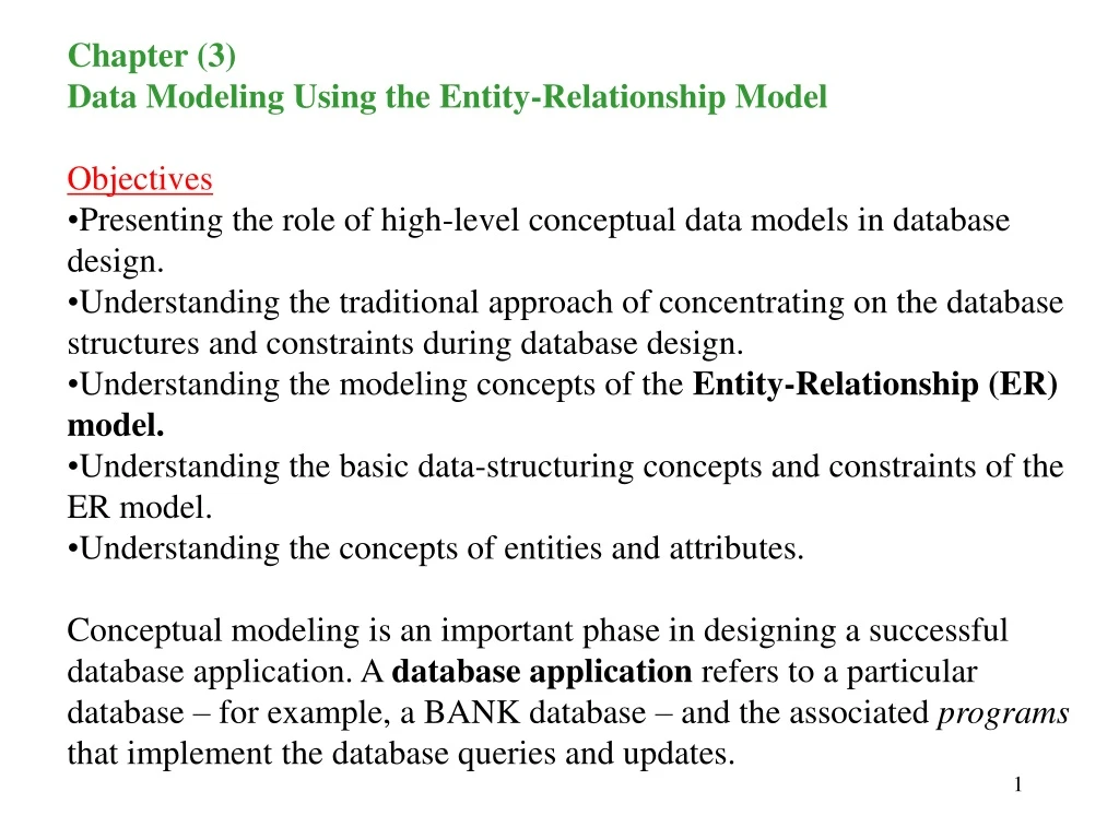
Chapter (3) • Data Modeling Using the Entity-Relationship Model • Objectives • Presenting the role of high-level conceptual data models in database design. • Understanding the traditional approach of concentrating on the database structures and constraints during database design. • Understanding the modeling concepts of the Entity-Relationship (ER) model. • Understanding the basic data-structuring concepts and constraints of the ER model. • Understanding the concepts of entities and attributes. • Conceptual modeling is an important phase in designing a successful database application. A database application refers to a particular database – for example, a BANK database – and the associated programs that implement the database queries and updates.
Main Topics • Using High-Level Conceptual Data Models for Database Design • An Example Database Application • Entity Types, Entity Sets, Attributes, and Keys • Relationships, Relationship Types, Roles, and Structural Constraints • Weak Entity Types • Refining the ER Design for the COMPANY Database • ER Diagrams, Naming Conventions, and Design Issues • Summary
Database Design Process Step (1a) – Requirements collection and analysis Database designer interviews prospective database users to understand and document their requirements. Step (1b) – Functional requirements of the application Consists of user defined operations (transactions) that will be applied to the database (retrieval and updates). Note: data flow diagrams, sequence diagrams, scenarios, etc .. Step (2) – Conceptual Design To create conceptual schema for the database using a high-level conceptual data model. The schema includes the concise description of the data requirements of the users and includes detailed descriptions on the entity types, relationships, and constraints.
Database Design Process – cont. Step (3) – Logical design (data model mapping) This step deals with the actual implementation of the database, using commercial DBMS. Step (4) – Physical design In this phase the the internal storage structures, access paths, and file organizations for the database files are specified.
An Example Database Application COMPANY database application. This database keeps track of: company’s employees, departments, and projects. Let’s see what are the things we may consider in our design: 1) Company is organized into departments. Each department has a unique name, a unique number, and a particular employee who manages the department. We want to keep track of the start date when that employee started managing the department. The locations of the department. 2) A department controls a number of projects. Each project has a unique name, a unique number, and a single location.
An Example Database Application – cont. 3) Employees information: Each employee has a name, a unique SSN, address, salary, sex, and DOB, The department to which he is assigned, The projects that he/she is working on, Number of hours per week that he/she works on each project, His/her direct supervisor. 4) Employees dependents: Each dependent’s first name, sex, DOB, and relationship to the employee. Having this in mind, can you design the schema?
An Example Database Application – cont. DEPARTMENT Name, Number, Manager, Start_Date, Location Think of questions you can ask? Remember, if you can connect two of them, then you should be able to ask a question that reflects such connections. PROJECT Name, Number, Location EMPLOYEE Name, SSN, Address, Salary, Sex, Bdate, Dept, Proj, Proj_hours DEPENDENT Name, Sex, Bdate, Relationship
Entity Types, Entity Sets, Attributes, and Keys The ER model describes data as entities, relationships, attributes. Entities and Their Attributes An entity is a “thing” in the real world with independent existence. Each entity has attributes which are the particular properties that describe it. EXPLOYEE : Name, age, SSN, … (Entity) (Attributes) A particular entity has values for its attributes. Several types of attributes occur in the ER model: simple vs. composite single-valued vs. multivalued stored vs. derived.
Composite vs. Simple (Atomic) Attributes Composite attributes can be divided into smaller subparts. Example: Address – Street Address, City, State, Zip Code, and Perhaps Country. The value of a composite attribute is usually the concatenation of subfieelds. There are times that the user refers to a composite attribute as a whole. In such cases, we do not need to separate the composite attribute in subfields.
Single-valued vs. Multivalued Attributes Most attributes have a single value for a particular entity. Example: Age is a single-valued attribute of an individual. In some cases there are more than one possibilities for the value of an attribute. Example: Students’ class. Color of cars. Stored vs. Derived Attributes In some cases the attribute does not exist in the database but its value can be derived by relating other attributes. Example: Age is something that can be derived from today’s date and the birth date. Today’s date and the birth date are the two that are stored in the database. Null Values In some cases a particular entity may not have an applicable value for an attribute. Example: Apartment Number in the ADDRESS entity.
Complex Attributes The composite and multivalued attributes can be nested in an arbitrary way. Example: Grouping components of a composite attribute between parentheses ( ), Separating the components with comma, and Displaying multivalued attributes between braces {}. Example: A person with more than one address and phone number. {AddressPhone({Phone(AreaCode, PhoneNumber)}, Address(StreetAddress(Number, Street, ApartmentNumber), City, State, Zip) )}
Entity Types, Entity Sets, Keys, and Value Sets A database may contain a group of entities that are similar. Example: The EMPLOYEE and COMPANY entities both have the same attributes. These have similar names but will take different values. An entity type defines a collection (or set) of entities that have the same attributes. The collection of all entities of a particular entity type in the database at any point in time is called an entity set. The entity set usually have the same name as the entity type. Example: EMPLOYEE refers to both a type of entity and the current set of all employee entities in the database. An entity type describes the schema or intention for a set of entities that share the same structure. A collection of entities of a particular entity type are grouped into an entity set, called extension of the entity type.
Key Attributes of an Entity Type The uniqueness constraint or key is very important in the design of a database. Example: SSN. On the ER diagram, the keys are shown underlined. Some entities may have more than one key. In such cases, the combination of the two must be unique. Example: LastName, FirstName …. (I know what you are going to ask) Example: Cars’ registration DB ((ABS 123, TX), TK629, Ford Mustang, convertible, 1998, {red,black}) Value Sets (Domains) of Attributes Each simple attribute of an entity type is associated with a value set (or domain of values). The set consists of the values that may be assigned to that attribute for each individual entity. Example: Age of employees 16-70.
A: E P(V), means: an attribute A of entity E whose value set is V can be defined as a function from E to the power set P(V) of V. A power set P(V) of a set V is the set of all subsets of V. The value of attribute A for entity e is represented as A(e). For a composite attribute A, the value V is the Cartesian product of P(V1), P(V2), …, P(Vn), where V1, V2, V3, …, Vnare the value sets of the simple component attributes that form A: V = P(V1)xP(V2)xP(Vn)x…xP(Vn). Example: Address: Street Address, P. O. Box, City, ZipCode, Country.
Initial Conceptual Design of the COMPANY Database We defined the entity types for the COMPANY database. DEPARTMENT DeptName, DeptNumber, Location, Manager, ManagerStartDate Key Key Multiple PROJECT PrjName, PrjNumber, Location, ControllingDepartment* Key Key EMPLOYEE Name, Address, Salary, EmpSSN, Sex, Bdate, DeptNumber, Supervisor Both Composite DEPENDENT SSN,Name, Sex, Bdate, Relationship
DEPARTMENT Name, Number, {Location}, Manager, ManagerStartDate PROJECT Name, Number, Location, Controlling Department EMPLOYEE Name (Fname, Minit, Lname), SSN, Sex, Address, Salary, BirthDate, Department, Supervisor, {WorksOn(Project, Hours) } DEPARTMENT Employee, DependentName, Sex, BirthDate, Relationship Figure 3.8 – Preliminary design of entity types for the COMPANY database
Relationships, Relationship Types, Roles, and Structural Constraints • Whenever an attribute from one entity type refer to an attribute in another entity type, some implicit relationships among the various entity types exist. • We need to discuss the: • Relationship Types, Sets, and Instances • Relationship Degree (binary, ternary), Role, and Recursive Relationships • Constrains on Relationship Types • Attributes of Relationship Types
Relationship Types A relationship type R among n entity types E1, E2, …, Endefines a set of associations or a relationship set among entities from these types. Mathematically, the relationship set R is a set of relationship instances ri, where each ri associates n individual entities (e1, e2, …, en ), and each entity e1 in r1is a member of entity type Ej , Informally, each relationship instance riin R is an association of entities, where the association includes exactly one entity from each participating entity type. Each ri represents the fact that the entities participating in ri are related in some way in the corresponding miniworld situation. Example: What is the relationship between EMPLOYEE and DEPARTMENT? Is order is important ?
Relationship Degree, Role Names, and Recursive Relationships Degree of Relationship Type is the number of participating entity types. Example: The WORKS_FOR relationship is of degree two, because 2 entities (EMPLOYEE and DEPARTMENT) are participating. A relationship of degree two is called binary. A relationship with degree three is called ternary. An example of a ternary relationship is SUPPLY shown on the figure on next page.
Relationship as Attributes It is sometimes convenient to think of a relationship type in terms of attributes. An attribute called Department of the EMPLOYEE entity type whose value for each employee entity is the department entity that the employee works for. Hence, the value set for this Department attribute is the set of all DEPARTMENT entities. When we think of a binary relationship as an attribute, we always have two options. Can you think of an example in the COMPANY DB?
Role Name and Recursive Relationships Each entity type that participates in a relationship type plays a particular role in the relationship. The role name signifies the role that a participating entity from the entity type plays in each relationship instance. It helps to explain what the relationship means. Example: in the WORKS_FOR relationship type, EMPLOYEE plays the role of employee or worker and DEPARTMENT plays the role of department or employer. In some cases the same entity type participate more than once in a relationship type in different roles. In such cases, the role name becomes essential for distinguishing the meaning of each participation. Such relationships types are called recursive relationships.
Constrains on Relationship Types Relationship types usually have certain constraints that limit the possible combinations of entities that may participate in the corresponding relationship set. The constraints are determined from the miniworld situation that the relationship represent. Example: Suppose each employee must work for only one department. Two main types of relationship constraints: cardinality ratio and participation. cardinality ratio: for a binary relationship specifies the number of relationship instances that an entity can participate in. Example: DEPARTMENT: EMPLOYEE is of cardinality ratio 1:N. What does this mean? Other possibilities are: 1:1, 1:N, N:1, and M:N (N:N).
Participation Constraints: This specifies whether the existence of an entity depends on its being related to another entity via the relationship type. There are two types of participations: totaland partial. Example for total: Every employee must work for a department. Example for partial: Some of the employees may manage some departments. Not all employees are managers. These two constraints are referred to as the structural constraints. On an ER model the total participation is shown as a double lines connecting the participating entity type to the relationship. The partial participation is represented by a single line.
Attributes of Relationship Types Relationships can also have attributes. Example: Suppose you add an attribute, Hours, to the WORKS_FOR relationship for number of hours that the employee works on a particular project. OR Add the starting date, StartDate, to the MANAGES relationships. The 1:1 or 1:N relationship types can be migrated to one of the participating entity types. Example: The StartDate attribute for the MANGES relationship can be an attribute of either EMPLOYEE or DEPARTMENT. For a 1:N relationship type, a relationship attribute can be migrated only to the entity type at the N-side of the relationship. Example: The WORKS_FOR relationship can include the StartDate. This can be added to the EMPLOYEE table as an attribute.
Weak Entity Types Entity types that do not have key attributes of their own are called weak types. The regular entity types that do have a key attribute are sometimes called strong entity types. Entities belonging to a weak entity type are identified by being related to specific entities from another entity type in combination with some of their attribute values. We call this other entity type the identifying or owner entity type. It is also called parent entity type. A weak entity type always has a total participation constraint. Example: A DRIVER_LICENSE entity cannot exist unless it is related to a PERSON entity. Note, DRIVER_LICENSE contains its unique key. Example: DEPENDENT entity … how ?
Weak Entity Types A weak entity type normally has a partial key, which is the set of attributes that can uniquely identify weak entries that are related to the same owner entity. Example: Suppose the children of each employee have unique first names. Thus, the Name in DEPENDENT entity can be used as the partial key. On an ER model, the weak relationships and entities are represented with double lines.
Refining the ER Design for the COMPANY Database • In our example, we specify the following relationship types: • MANAGES, a 1:1 relationship type between EMPLOYEE and DEPARTMENT. EMPLOYEE participation is partial. DEPARTMENT participation is not clear from the requirements. We question the users, who say that a department must have a manager at all times, which implies total participation. The attribute StartDate is assigned to this relationship type. • WORKS_FOR, a 1:N relationship type between DEPARTMENT and EMPLOYEE. Both participations are total. • CONTROLS, a 1:N relationship type between DEPARTMENT and PROJECT. The participation of PROJECT is total, whereas that of DEPARTMENT is determined to be partial, after consultation with the users.
Refining the ER Design for the COMPANY Database • 4. SUPERVISION, a 1:N relationship type between EMPLOYEE (in the supervisor role) and EMPLOYEE (in the supervisee role). Both participations are determined to be partial, after the users indicate that not every employee is a supervisor and not every employee has a supervisor. • 5. WORKS_ON, determined to be an M:N relationship type with attribute Hours, after the users indicate that a project can have several employees working on it. Both participations are determined to be total. • 6. DEPENDENTS_OF, a 1:N relationship type between EMPLOYEE and DEPENDENT, which is also the identifying relationship for the weak entity type DEPENDENT. The participation of EMPLOYEE is partial, whereas that of DEPENDENT is total.
Design Choices for ER Conceptual Design • In general, the schema design process should be considered an iterative refinement process, where an initial design is created and then iteratively refined until the most suitable design is reached. Some of the refinements that are often used include the following: • A concept may be first modeled as an attribute and then refined into a relationship because it is determined that the attribute is a reference to another entity type. It is often the case that a pair of such attributes that are inverses of one another are refined into a binary relationship. • Similarly, an attribute that exists in several entity types may be refined into its own independent entity type. For example, suppose that several entity types in a UNIVERSITY database, such as STUDENT, INSTRUCTOR, and COURSE each have an attribute Department in the initial design; the designer may then choose to create an entity type DEPARTMENT with a single attribute DeptName and relate it to the three entity types (STUDENT, INSTRUCTOR, and COURSE) via appropriate relationships. Other attributes/relationships of DEPARTMENT may be discovered later.
Design Choices for ER Conceptual Design – cont. • 3. An inverse refinement to the previous case may be applied—for example, if an entity type DEPARTMENT exists in the initial design with a single attribute DeptName and related to only one other entity type STUDENT. In this case, DEPARTMENT may be refined into an attribute of STUDENT.
Summary • We learned about, • modeling concepts of a high-level conceptual data model, ER model. • We talked about: • Simple or atomic • Composite • Multivalued • We also briefly discussed stored versus derived attributes. We then discussed the ER model concepts at the schema or "intension" level: • Entity types and their corresponding entity sets. • Key attributes of entity types. • Value sets (domains) of attributes. • Relationship types and their corresponding relationship sets. • Participation roles of entity types in relationship types. • We presented two methods for specifying the structural constraints on relationship types. The first method distinguished two types of structural constraints: • Cardinality ratios (1:1, 1:N, M:N for binary relationships) • Participation constraints (total, partial)