Download
1 / 47
520 likes | 842 Views
Design Methodology. 100,000,000. 10,000,000. 1,000,000. 10,000,000. 100,000. 58%/Yr. compound. 1,000,000. Complexity growth rate. 10,000. 100,000. Logic Transistors per Chip (K). Productivity (Trans./Staff-Month). 10,000. 1,000. 100. 1,000. Productivity growth rate. 10. 100.

E N D
100,000,000 10,000,000 1,000,000 10,000,000 100,000 58%/Yr. compound 1,000,000 Complexity growth rate 10,000 100,000 Logic Transistors per Chip (K) Productivity (Trans./Staff-Month) 10,000 1,000 100 1,000 Productivity growth rate 10 100 21%/Yr. compound 1981 1985 1989 1993 1997 2001 2005 2009 The Design Productivity Challenge Logic Transistors per Chip (K) Productivity (Trans./Staff-Month) 1981 1983 1985 1987 1989 1991 1993 1995 1997 1999 2001 2003 2005 2007 2009 A growing gap between design complexity and design productivity Source: ITRS’97
The Custom Approach Intel 4004 Courtesy Intel
Intel 4004 (‘71) Intel 8080 Intel 8085 Intel 80486 Intel 80286 Transition to Automation and Regular Structures Courtesy Intel
Automating Design • Exploitation By Algorithms • Regular Structures • Logic Synthesis • Regularization of Connection • Floorplanning (Localization of function) • System Level Performance/Power/Cost • Allocation of Physical Resources • Communication/Interconnect • Hierarchy based on Sensitivity to Latency • Wires to Link Protocols
A System-on-a-Chip: Example Courtesy: Philips
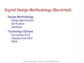
Design Methodology • Design process traverses iteratively between three abstractions: behavior, structure, and geometry • More and more automation for each of these steps
Floorplanning A Protocol Processor for Wireless
Digital Circuit Implementation Approaches Custom Semicustom Cell-based Array-based Standard Cells Pre-diffused Pre-wired Ma cro Cells Compiled Cells (Gate Arrays) (FPGA's) Implementation Choices
Impact of Implementation Choices 100-1000 Domain-specific processor (e.g. DSP) 10-100 Embedded microprocessor Energy Efficiency (in MOPS/mW) 1-10 Hardwired custom Configurable/Parameterizable 0.1-1 Somewhat flexible Flexibility(or application scope) Fully flexible None
Implementation Strategies • PLA • Technology confined in cell macros (tiling) • Cell based logic • Technology confined to cells (area) • Both 1-d and 2-d solutions • Transistor Arrays (Gate arrays) • Technology confined to layers (Below M1 fixed)
Product terms x x 0 1 x 2 AND OR plane plane f f 0 1 x x x 0 1 2 PLA: Programmable Logic Array
Two-Level Logic Every logic function can beexpressed in sum-of-productsformat (AND-OR) minterm Inverting format (NOR-NOR) more effective
Or-Plane And-Plane V f GND DD PLA Layout – Exploiting Regularity
Breathing Some New Life in PLAs River PLAs • A cascade of multiple-outputPLAs. • Adjacent PLAs are connected via river routing. • No placement and routing needed. • Output buffers and the input buffers of the next stage are shared. Courtesy B. Brayton
Experimental Results Area: RPLAs (2 layers) 1.23 SCs (3 layers) - 1.00, NPLAs (4 layers) 1.31 Delay RPLAs 1.04 SCs 1.00 NPLAs 1.09 Synthesis time: for RPLA , synthesis time equals design time; SCs and NPLAs still need P&R. Also: RPLAs are regular and predictable Layout of C2670 Standard cell, 2 layers channel routing Standard cell, 3 layers OTC Network of PLAs, 4 layers OTC River PLA, 2 layers no additional routing
2-d Cell Based: “Hard” Modules 25632 (or 8192 bit) SRAM Generated by hard-macro module generator
1-d Cell-based Design (standard cells) Feedthrough cell Logic cell Routing channel Rows of cells Functional Routing channel requirements are reduced by presence of more interconnect layers module (RAM, multiplier, )
Standard Cell — Example [Brodersen92]
Standard Cell – The New Generation Cell-structure hidden underinterconnect layers
Standard Cell - Example 3-input NAND cell (from ST Microelectronics): C = Load capacitance T = input rise/fall time
“Soft” MacroModules Synopsys DesignCompiler
The “Design Closure” Problem Iterative Removal of Timing Violations (white lines) Courtesy Synopsys
Gate Array — Sea-of-gates Uncommited Cell Committed Cell(4-input NOR)
Sea-of-gate Primitive Cells Using oxide-isolation Using gate-isolation
Sea-of-gates Random Logic Memory Subsystem LSI Logic LEA300K (0.6 mm CMOS) Courtesy LSI Logic
The return of gate arrays? Via programmable gate array(VPGA) Via-programmable cross-point metal-6 metal-5 programmable via Exploits regularity of interconnect [Pileggi02]
Pre-wired Arrays: Classification of prewired arrays (or field-programmable devices): • Based on Programming Technique • Fuse-based (program-once) • Non-volatile EPROM based • RAM based • Programmable Logic Style • Array-Based • Look-up Table • Programmable Interconnect Style • Channel-routing • Mesh networks
Fuse-Based FPGA antifuse polysilicon ONO dielectric n antifuse diffusion + 2 l Open by default, closed by applying current pulse From Smith’97
I I I I I I 5 4 3 2 1 0 Programmable I I I I 3 2 1 0 I I I I I I OR array 5 4 3 2 1 0 Fixed AND array O O O O O 3 2 1 0 O 0 0 Indicates programmable connection Indicates fixed connection Array-Based Programmable Logic Programmable OR array Fixed OR array Programmable AND array Programmable AND array O O O O O O 3 2 1 3 2 1 PLA (flexible – sizing) PROM (dense) PAL (uniform load)
1 X X X 2 1 0 : programmed node NA NA f f 1 0 Programming a PROM
Configuration A B S F= 0 0 0 0 0 X 1 X 0 Y 1 Y 0 Y X XY X 0 Y XY Y 0 X X Y Y 1 X X +Y 1 0 X X 1 0 Y Y 1 1 1 1 2-input mux as programmable logic block A 0 F B 1 S
A B 1 SA Y 1 C D 1 SB S0 S1 Logic Cell of Actel Fuse-Based FPGA
4 C ....C 1 4 H1 H2 H0 EC S/R D Bypass 4 control Logic Din F’ G’ H’ YQ D SD function D Q 3 D F 2 D 1 Logic EC RD function G’ H’ H 1 Y F 4 S/R Bypass Logic control XQ F Din F’ G’ H’ SD 3 function D Q F 2 G F 1 EC RD clock 1 H’ X F’ Multiplexer Controlled Xilinx 4000 Series by Configuration Program LUT-Based Logic Cell Courtesy Xilinx
Array-Based Programmable Wiring Interconnect Point Programmed interconnection Input/output pin Cell Horizontal tracks Vertical tracks
Mesh-based Interconnect Network Switch Box Connect Box InterconnectPoint Courtesy Dehon and Wawrzyniek
Transistor Implementation of Mesh Courtesy Dehon and Wawrzyniek
Hierarchical Mesh Network Use overlayed mesh to support longer connections Reduced fanout and reduced resistance Courtesy Dehon and Wawrzyniek
Altera MAX From Smith97
t PIA LAB1 LAB2 PIA t PIA LAB6 Altera MAX Interconnect Architecture column channel row channel LAB Array-based (MAX 3000-7000) Mesh-based (MAX 9000) Courtesy Altera
Field-Programmable Gate ArraysFuse-based Standard-cell like floorplan
Xilinx 4000 Interconnect Architecture 12 Quad 8 Single 4 Double 3 Long Direct 2 CLB Connect 3 Long 12 4 4 8 4 8 4 2 Quad Long Global Long Double Single Global Carry Direct Clock Clock Chain Connect Courtesy Xilinx
RAM-based FPGA Xilinx XC4000ex Courtesy Xilinx
RAM 500 k Gates FPGA + 1 Gbit DRAM Preprocessing Multi- Spectral Imager Analog 64 SIMD Processor Array + SRAM Image Conditioning 100 GOPS mC system +2 Gbit DRAM Recog- nition Design at a crossroadSystem-on-a-Chip • Embedded applications: cost,performance, and energy are the issues! • DSP and control intensive • Mixed-mode • Software design is crucial
Addressing the Design Complexity IssueArchitecture Reuse Reuse comes in generations
Heterogeneous Programmable Platforms FPGA Fabric Embedded memories Embedded PowerPc Hardwired multipliers Xilinx Vertex-II Pro High-speed I/O Courtesy: Xilinx
Summary • Design Choice forced by System Tradeoffs • Deep Sub-micron Challenges • Regularity (Design flexibility at smallest scales) • Power consumption! • Interconnection Parasitics • Nanoscopic Devices/Modules New circuit solutions are bound to emerge • Who can afford design in the years to come?