Download
1 / 27
270 likes | 432 Views
Military Health System (MHS) Future State Work Group (FSWG) In Progress Review (IPR). Business Software Architecture (BSA) Specified by Software Definition Framework (SDF) Supporting Integrated Requirements Design (IRD) Sets of Integrated Management Information Within

E N D
Military Health System (MHS)Future State Work Group (FSWG)In Progress Review (IPR) Business Software Architecture (BSA) Specified by Software Definition Framework (SDF) Supporting Integrated Requirements Design (IRD) Sets of Integrated Management Information Within Business Capabilities Lifecycle (BCL) See Companion Papers for Details “Guidelines for IRD Process and DODAF Products within the BCL”, “SBusiness Services Architecture (BSA) Services Definition Framework (SDF)” And “Healthcare SOA Reference Architecture (H-SOA-RA)” Send updates to Stephen.Hufnagel.ctr@tma.osd.mil, editor Last updated 10 Oct 07 Working Document; Not for Public Release
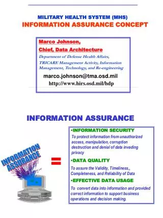
EXECUTIVE SUMMARY:The objective of the Software Definition Framework (SDF) is to specify software components and their services within an Enterprise Architecture (EA), also known as a Business Software Architecture (BSA). The objective of the Integrated Requirements and Design (IRD) process is to guide investment portfolio, acquisition managers and engineers with the appropriate Software Development Lifecycle (SDLC) documentation needed for the Business Capability Lifecycle (BCL) of a Business Transformation Architecture (BTA). The SDF defines a BSA that supports the SDLC by specifying IRD solution sets which become part of the BCL “Integrated Management Information” (e.g., within the center purple box of the following figure). This “Integrated Management Information” should contain a “future state” strategic architecture and a BTA transition plan composed of IRD solution sets. Both the “future state” enterprise architecture and BTA transition plan are composed of SDF views and related artifacts, as shown in the following slides. EXECUTIVE ORDER#13335 and #13410 mandate federal agencies to have interoperable Electronic Healthcare Records (EHR), as specified by the Health and Human Services (HHS) Healthcare Information Technology Standards Panel (HITSP). See the companion paper and brief, which discusses the MHS-VA standardized “Healthcare SOA Reference-Architecture (H-SOA-RA)” for categorizing, describing and constructing system functional components within a HITSP compliant Enterprise Service Oriented Architecture (SOA).
Performance Models Business Rules Business Software Architecture (BSA) MHS Strategic Vision Support the Core Mission Areas with high-quality, low-cost, aligned, interoperable and agile Healthcare Information Systems (HIS) Clinical FHP Logistics & Readiness Financial & Budget TMA Operations MHS CIO Core Mission Areas Business Value Chain Segments Business Process Models Information Models Solution Architectures Service Oriented Architectures
KEY CONCEPT:Business Software Architecture (BSA)Components are Specified by theSoftware/Service Definition Framework (SDF)
Notional Time/Cost of IRD Process IRD 1.6 Define Quality Assessment Attributes Year of Execution Note: Coefficient “C” varies depending on submission size IRD 1.5 Refine Funded Solution IRD 1.4 Prioritize Solution Sets C*10 Hours C* 100 Hours C* 1000 Hours C*10,000 Hours C*100,000 Hours IRD 1.3 Conduct Enterprise Analysis of Requirements-Design Sets IRD 1.2 Process Submission • COMPETING OBJECTIVES: • Minimize costs of IRD phases 1.1, 1.2, 1.3 and 1.4 • Make changes and fix problems as early as possible IRD 1.1 Conduct Strategic Generation of IT Requirements IRD 1.1 IRD 1.2 IRD 1.3 IRD 1.4 IRD 1.5 IRD 1.6
Notional ROI of IRD Process Cost to make changes or fix problems C*1 C*10 C*100 C*1,000 C*10,000 10X 100X Cost of Sustainment • https://www.thedacs.com/databases/roi/display_all_facts.php?datasource=ROI&label=Cleanroom&improvement2=Cleanroom • Basili, V., McGarry, F., Page, G., Pajerski, R., Waligora, S., Zelkowitz, M., "Software Process Improvement in the NASA Software Engineering Laboratory", Technical Report CMU/SEI-94-TR-22, December 1994, Carnegie Mellon University, Pittsburgh, Pennsylvania: Software Engineering Institute. • Sherer, S. W., Kouchakdjian, A., Arnold, P. A., "Experience Using Cleanroom Software Engineering", IEEE Software, May 1996, pp. 69 - 76. IRD 1.1 IRD 1.2 I RD 1.3 IRD 1.4 I RD 1.5 IRD 1.6 Sustainment Note: Coefficient “C” varies depending on submission size Notional 5 to 10:1 ROI Six Sigma 1X 10X Cost of Software Engineering
IRD Creation of BCL “Integrated Management Information” SDF Artifacts
IRD Creation of BCL “Integrated Management Information” DODAF Artifacts
SDF DODAF
High Level Overview of Future State Framework and its use within the IRD process The future state architecture group has developed a first version of a Future State Framework (the “Framework” hereafter) to be followed and complemented by appropriate Future State architecture content and supporting artifacts. The Framework, while having a COTS version as a starting point, is being adapted to MHS needs. It includes a series of interrelated “views” which are defined in an UML model. The Framework supports the IRD process and the MHS Enterprise Architecture (EA). Central to the Framework is the support for Requirements-Design Sets from the from the capability/change request inception, through acquisition and deployment. There are three views which are meant to be extensively used in the initial IRD phases: Business View, Solution View, Software Specification View. Each view should increasingly become more detailed as the IRD process advances towards acquisition and later on towards deployment: • The Business View supports concepts such as Capability which is further detailed by Processes, Subprocesses, Elementary Processes. • The Solution View is defined in terms of Use Cases involving Actors and Use Case Steps. Use cases may be composites of other use cases and a set of requirements quite often is described as a collection of use cases. • The Software Specification View relies on concepts which include Transaction. A transaction can further contain transactions at increasingly lower levels. These three views may be linked at a higher level (Capabilities, Processes, Use case are supported by some software specifications) but they may be further linked at various lower levels by appropriate choices of transactions associated to use case steps or elementary processes. Thus in a Requirement-Design set one may choose to pair in a flexible manner elements from the requirement side with elements from the design side, maintaining visibility and understanding for all stakeholders involved. One can also control the cost of the IRD process by calibrating the level of details of the required views at various decision points during the IRD process starting with the Triage step and continuing through the investment decision phase and further through acquisition, deployment and other phases deemed necessary. A completed IRD package for acquisition purposes will have also (partial and incomplete) Framework Implementation, Deployment and Runtime views covering constraints, compliance and other aspects (such as network and communications specifications). These views will be completed after the acquisition phase by contractors, vendors and other entities as they become involved during the software development and deployment lifecycle. The Framework views aim to allow for the recording of information sufficient for deriving various compliance artifacts (such as DoDAF OVs and SVs). The Framework needs to be extended in several directions including the areas of: Security, Testing, Error Handling, Federation.
UML RelationshipsAmong Classes and Objects Association:a solid line represents an unspecified relationship between classes or objects; Optional open arrowheads indicate flow (e.g. messaging) Association - Composition: a solid line with an open arrowhead and a solid diamond at the tail end that represents a "has-a" relationship. The arrow points from the containing to the contained class. A composition models the notion of one object "owning" another and thus being responsible for the creation and destruction of another object. Association - Aggregation: a solid line with an open arrowhead and a hollow diamond at the tail end that represents a "has-a" relationship. The arrow points from the containing to the contained class. An aggregation models the notion that one object uses another object without "owning" it and thus is not responsible for its creation or destruction. Generalization - Inheritance: a solid line with a solid arrowhead that represents an “is-a” relationship. The arrow points from a sub-class to a super-class or from a sub-interface to its super-interface. Generalization - Implementation: a dotted line with a solid arrowhead that points from a class to the interface that it implement Generalization - Realize: a dotted line with a solid arrowhead shows that the source object implements or realizes the destination. Realize is used to express traceability in the model. Dependency: a dotted line with an open arrowhead that shows one entity depends on the behavior of another (e.g., Realization, Instantiation and Usage) client (tail) refines the source. Typical usages are to represent that one class instantiates another or uses the other as an input parameter. Message: a solid line with an open arrowhead that shows that one entity communicates with another.