Download
1 / 33
360 likes | 530 Views
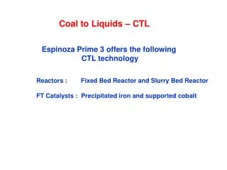
Coal to Liquids – CTL. Espinoza Prime 3 offers the following CTL technology. Reactors : Fixed Bed Reactor and Slurry Bed Reactor FT Catalysts : Precipitated iron and supported cobalt. FISCHER-TROPSCH REACTION. For Iron and Cobalt catalysts. SYNTHESIS GAS (SYNGAS)

E N D
Coal to Liquids – CTL Espinoza Prime 3 offers the following CTL technology Reactors : Fixed Bed Reactor and Slurry Bed Reactor FT Catalysts : Precipitated iron and supported cobalt
FISCHER-TROPSCH REACTION For Iron and Cobalt catalysts SYNTHESIS GAS (SYNGAS) C SOURCE + H2O + O2 CO + H2 + CO2 + H2O (Same) FT REACTION n CO + n(2+x) H2 (CH(2+2x))n + n H2O (Similar) WGS REACTION CO + H2O CO2 + H2 Fe >> Co
Distillation Column Hydrocracker Light HC Separator Light HC H2 Water Syngas cleaning Wax Naphtha Diesel Secondary wax cleaning Wax H2 Hydrogenation Fischer- Tropsch Reactor Wax Recycled to extinction A SIMPLIFIED FT – PU Process Flow Diagram
Espinoza Prime 3 Technological Preferences Precipitated Fe catalyst No Yes Supported Co catalyst Yes No Fixed Bed Slurry Bed
Espinoza Prime 3 Technological Preferences Fe Co Fixed Bed Slurry Bed
Influence of Plant Size on Technology Selection Plant capacity : 1000 to 3500 bpd FB - Co cat SBR – Fe cat Fe Co Fixed Bed Slurry Bed
Influence of Plant Size on Technology Selection Plant capacity : 4000 to 10000 bpd SBR - Fe cat FB - Co cat Fe Co Fixed Bed Slurry Bed
Influence of Plant Size on Technology Selection Plant capacity : > 10000 bpd From : To :
Espinoza Prime 3 Technological Preferences Precipitated Fe catalyst Yes Supported Co catalyst Yes Fixed Bed Slurry Bed
Fixed Bed FT Reactors Poisons remain at the top PH2O increase, Gas Lin Vel decrease (lower heat transfer), High ΔP Diameter ~ 1.5 – 2” Lower heat transfer region PH2O and heat transfer at Rx bottom limit conversion
Slurry Bed FT Reactors Continuous slurry movement. All cat inventory exposed to poisons Good heat transfer at any point ΔP = gas distributor plus hydrostatic Conversion limited by max PH2O inside reactor (towards top) Diameter ~ up to 34’
Typical Preparation Stages for the Precipitated Fe Catalyst
Iron Catalysts Iron catalysts have a high WGS activity during FT reaction while cobalt catalysts do not. Result : The H2/CO ratio increases during reaction.
COBALT CATALYSTS • Typically supported on an inorganic oxide • - Alumina, silica, titania, zirconia, zinc oxide, mixtures • - 10-35 wt% cobalt loading • - Typical finished catalyst cost in range of $10-30/lb • Usually with precious metal reduction promoter • - Ruthenium, rhenium, platinum, etc. • Other additives sometimes employed • - Rare earth oxides, base metals, alkalis • Must be reduced to the metal prior to reaction • - Hydrogen treatment at up to about 700-750° F
Supported Co Catalysts Radial Co Concentration Profile: Bad Impregnation Diffusion constraints, Low metal area Metal concentration
Supported Co Catalysts Radial Co Concentration Profile: Good Impregnation Metal concentration * We pay particular attention to the radial Co concentration profile
Frequency Low metal surface Easier reduction Higher stability High metal surface Difficult reduction Fast deactivation Cobalt crystallite size Co Metal Crystallites: Effect of their Size * Our supported Co catalyst for fixed bed reactors has the optimum average crystallite size
Typical Syngas Composition from Different Gasifiers (vol %)
WGS to Adapt the H2/CO in Feed for Cobalt and Iron Applications
WGS to Adapt the H2/CO in Feed for Cobalt and Iron Applications
Both catalysts show a similar performance in terms of carbon efficiency when using a coal derived syngas feed. Comparison of Cobalt and Iron Performance
COST OF FEED(S) CLEANING FOR Fe AND Co CATALYSTS Co Catalysts Fe Catalysts EXTRA COST FOR Co CATALYSTS CLEANING COST 0.001’s 0.01’s 0.1’s 1’s 10’s S CONTAMINANT LEVEL (ppm) The S compounds in the feed for both catalysts have to be very low, but cobalt catalysts require an additional step to go from the low 100’s ppb (eg ~ 200) for Fe catalysts to the low 10’s (eg ~ < 20) ppb. 32
Differences in the Fe and Co Based Processes Due to Irreversible Poisons in the Feed Fe BASED PROCESS H2O O2 Source CO2 Removal H2O Coal Syngas Cleanup FT Reactor Water Gas Shift Gasifier H2/CO ~ 1.6 - 1.9 ~ 200 ppb S (*) Co BASED PROCESS H2O O2 Source CO2 Removal H2O Coal Additional Syngas Cleanup Syngas Cleanup FT Reactor Water Gas Shift Gasifier H2/CO ~ 2.05 – 2.1 ~ 20 ppb S (*)M E Dry