Download
1 / 26
260 likes | 275 Views
This article discusses the progress and plans for the development of the Ball Aerospace Optical Autocovariance Wind Lidar (OAWL) system. It explains the concept of optical autocovariance lidar, its applications, and the development program for the OAWL. The article also introduces the Integrated Direct Detection (IDD) wind lidar approach and the OAWL receiver design using polarization multiplexing.

E N D
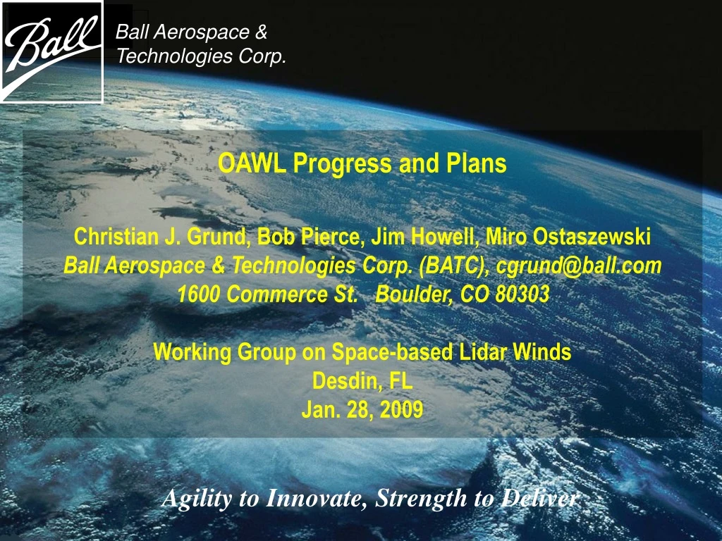
Ball Aerospace & Technologies Corp. OAWL Progress and PlansChristian J. Grund, Bob Pierce, Jim Howell, Miro OstaszewskiBall Aerospace & Technologies Corp. (BATC), cgrund@ball.com1600 Commerce St. Boulder, CO 80303Working Group on Space-based Lidar WindsDesdin, FLJan. 28, 2009 Agility to Innovate, Strength to Deliver
Acknowledgements: The Ball OAWL Development Team Jim Howell – Systems Engineer, Aircraft lidar specialist, field work specialist Miro Ostaszewski – Mechanical Engineering Dina Demara – Software Engineering Michelle Stephens – Signal Processing, algorithms Mike Lieber – Integrated system modeling Chris Grund – PI system architecture, science/systems/algorithm guidance, electrical engineering Carl Weimer – Space Lidar Consultant Ball Aerospace & Technologies
Optical Autocovariance Wind Lidar and the Integrated Direct Detection Wind Lidar Concepts
What is Optical Autocovariance Lidar? • Method: • Interferometric direct detection lidar • Instantaneous measurement of the phase and amplitude of the optical autocovariance function (OACF) about one Optical Path Difference (OPD) • Key Attributes: • Very high spectral resolution feasible • Self-referenced optical mixing • intensity measurements determine optical freq. • minimizes required electronic bandwidth • minimizes required signal processing power • Eliminates need to tune receiver to transmitter • Hardware-free compensation for LOS orbital V • Applications: • Doppler Lidar (wind profiles) • High Spectral Resolution Lidar (HSRL) • Differential Absorption Lidar (DIAL) Ball Aerospace & Technologies
Optical Autocovariance Wind Lidar (OAWL) • The phase of the OACF for 0-velocity at 0-range is captured by locally sampling the outgoing pulse. • The OACF is measured for the atmospheric return from each range bin. • The wind velocity V is calculated from the difference in the OACF phase (Df) between the 0-velocity sample and each range return: V = l *Df * c / (2 * OPD) Df expressedas a fraction of 1 OACF period Doppler Winds use the Phase of the OACF Ball Aerospace & Technologies
Addressing the Decadal Survey 3D-Winds Mission withAn Efficient Single-laser All Direct Detection Solution Most Efficient: Integrated Direct Detection (IDD) wind lidar approach: • Double-edge etalon strips and measures the molecular, rejects most of the aerosol component. • OAWL HSRL retrieval determines residual aerosol/molecular mixing ratio • Etalon processes molecular backscatter winds, corrected by HSRL from OAWL for aer/mol backscatter mixing ratio • Result: • single-laser transmitter, single wavelength system • single simple, low power and mass signal processor • full atmospheric profile using aerosol and molecular backscatter signals • OAWL alone can measure both, however power*aperture*precision optimization is less efficient (a trade) Ball Aerospace patents pending Molecular WindsUpper atmosphere profile Etalon Molecular Receiver OAWL Aerosol Receiver Combined Signal Processing Telescope 1011101100 Full Atmospheric Profile Data Aerosol Winds Lower atmosphere profile UV Laser HSRL Aer/mol mixing ratio Ball Aerospace & Technologies
Optical Autocovariance Wind Lidar (OAWL) Development Program • Internal investment to develop the OAWL theory and implementable architecture, performance model, perform proof of concept experiments, and design and construct a flight path receiver prototype. • Recent NASA IIP win will take OAWL receiver at TRL-3, build into a robust lidar system, fly on the WB-57, exit at TRL-5. Ball Aerospace & Technologies
Ball Multi-wavelength OA Receiver IRAD Status Ball Aerospace & Technologies
OAWL IRAD Receiver Design Uses Polarization Multiplexing to Create 4 Interferometers in the Same space • Mach-Zehnder-like interferometer allows 100% light detection on 4 detectors • Cat’s-eyes field-widen and preserve interference parity allowing wide alignment tolerance, practical simple telescope optics • Receiver is achromatic, facilitating simultaneous multi-l operations (multi-mission capable: Winds + HSRL(aerosols) + DIAL(chemistry)) • Very forgiving of telescope wavefront distortion saving cost, mass, enabling HOE optics for scanning and aerosol measurement • 2 input ports facilitating 0-calibration Ball Aerospace & Technologies patents pending
Solid Model of Receiver (detector covers removed) • - All aluminum construction minimizes DT, cost • - Athermal interferometer design • - Factory-set operational alignment • for autonomous aircraft operation • - ≈100% opt. eff. to detector • - multi-l winds, plus HSRL and depolarization for • aerosol characterization • and ice/water cloud • discrimination • - Compatible with wind and HSRL measurements Detectors: 1 532nm depolarization 1 355nm depolarization 4 532nm winds/HSRL 4 355nm winds/HSRL 10 Total Ball Aerospace & Technologies
OAWL Receiver Mechanical Components • A few simple components • Detector housings • Monolithic interferometer • Covers and base plate • mount to a monolithic base structure. • Detector amplifiers and thermal controls • are housed inside the base structure. Ball Aerospace & Technologies
Initial Static Interferometer Stability Tests For these measurements the OAWL receiver is supported on the ends- worst case support scinario Ball Aerospace & Technologies
2nd Tightening First tightening All Aluminum Interferometer Supported by Endsno isolation,before/after repeated bolting and unbolting of the bottom plate • Bottom access plate removal: fringe tilt returns with reinstallation of bottom – GOOD! • Static load: 2 kg suspended at center – no fringe shift or rotation - GOOD! • Thermal: ~1 fringe side drift /hr in unprotected laboratory environment – GOOD! Flat mirrors Interferometer out to TV Camera Ball Aerospace & Technologies
OAWL Receiver IRAD Progress Schedule and Status Receiver Status (Ball internal funding): • Optical design PDR complete Sep. 2007 • Receiver CDR complete Dec. 2007 • Receiver performance modeled complete Jan. 2008 • Design complete Mar. 2008 • COTS Optics procurement complete Apr. 2008 • Major component fabrication complete Jun. 2008 (IIP begins------------------------------------------------------------------------ Jul. 2008) • Custom optics procurement vendor issues Aug. 2008 • Custom optics procurement complete Dec. 2008 • Assembly and Alignment in progress Jan. 2009 • Preliminary testing scheduled Mar. 2009 • Delivery to IIP scheduled Late Mar. 2009 Ball Aerospace & Technologies
OAWL System IIP and Status Ball Aerospace & Technologies
OAWL IIP Objectives • Demonstrate OAWL wind profiling performance of a system designed to be directly scalable to a space-based direct detection DWL (i.e. to a system with a meter-class telescope 0.5J, 50 Hz laser, 0.5 m/s precision, with 250m resolution). • Raise TRL of OAWL technology to 5 through high altitude aircraft flight demonstrations. • Validate radiometric performance model as risk reduction for a flight design. • Demonstrate the robustness of the OAWL receiver fabrication and alignment methods against flight thermal and vibration environments. • Validate the integrated system model as risk reduction for a flight design. • Provide a technology roadmap to TRL7 Ball Aerospace & Technologies
OAWL IIP Development Plan Shake & Bake Receiver: Validate system design Integrate the OAWL Receiver (Ball IRAD) (entry TRL 3 (or 2.5 since the POC receiver uses same principles but is of a different architecture ) Into a lidar system (add laser, telescope, frame, data system, isolation, and autonomous control software in an environmental box) Validate Concept, Design, and Wind Precision Performance Models from the NASA WB-57 aircraft (exit TRL 5) Ball Aerospace & Technologies
IIP System Concept for WB-57 Tests Pallet Cover 6’ Pallet (WB-57 form factor) Custom Pallet-Mounting Frame Telescope IRAD - Receiver Laser Source Custom Window Ball Aerospace & Technologies
Platteville, CO Houston, TX Boulder, CO Leg 1 Leg 2 Multipass ** Wind profilers in NOAA operational network OAWL Validation Field Experiments 1. Ground-based-looking up Side-by-side with the NOAA High Resolution Doppler Lidar (HRDL) 2. Airborne OAWL vs. Ground-based Wind Profilers and HRDL (15 km altitude looking down along 45° slant path (to inside of turns). Many meteorological and cloud conditions over land and water) Fall 2009 Fall 2010 Ball Aerospace & Technologies
Taking an OAWL Lidar System Through TRL 5 NASA/ESTO Funded IIP Plan: • Program start, TRL 3 complete Jul. 2008 • IRAD receiver delivered to IIP planned Mar. 2009 • Receiver shake and bake (WB-57 level) assume 3/1/09 deliveryMar. 2009 • System PDR/CDR planned Feb./Mar. 2009 • Lidar system design/fab/integration design in progress Oct. 2009 • Ground Tests completed planned Mar. 2010 • Airborne tests complete (TRL-5)planned Dec. 2010 • Receiver shake and bake 2 (launch level) planned Apr. 2011 • tech road mapping (through TRL7)planned May 2011 • IIP Complete planned June 2011 Ball Aerospace & Technologies
Conclusions • Optical Autocovariance Wind Lidar offers high performance wind measurements from aerosol backscatter at 355 nm. • OAWL aerosol and Double-edge Etalon molecular wind measurements can be made simultaneously and efficiently at 355nm. • IRAD Receiver: All components meeting required specs in house, final assembly/alignment in progress. Vendor performance issues overcome. • IIP in progress: OAWL Receiver TRL 2.5 OAWL system Ground Tests Airborne Tests TRL 5 • Plan ground testing in late Fall 2009 along side NOAA Doppler lidar • Plan WB-57 flight tests in Fall 2010 Ball Aerospace & Technologies
Altitude (km) Volume backscatter cross section at 355 nm (m-1sr-1) Ball-internally funded Space-based OA Radiometric Performance Model –Model Parameters: Realistic Components and Atmosphere LEO Model Parameters: Wavelength 355 nm, 532 nm Pulse Energy 550 mJ Pulse rate 50 Hz Receiver diameter 1m (single beam) LOS angle with vertical 450 Vector crossing angle 900 Horizontal resolution* 70 km (500 shots) System transmission 0.35 Alignment error 5 mR average (NOTE: ~50 mR allowed) Background bandwidth 35 pm Orbit altitude 400 km Vertical resolution 0-2 km, 250m 2-12 km, 500m 12-20 km, 1 km Phenomenology CALIPSO model l-scaled validated CALIPSO Backscatter model used. (l-4 molecular, l-1.2 aerosol) Model calculations validated against short range POC measurements. Ball Aerospace & Technologies
1km Vertical Averaging (Resolution) 500 m Threshold/Demo Mission Requirements 250 m Objective Mission Requirements OAWL – Space-based Performance: Daytime, OPD 1m, aerosol backscatter component, cloud free LOS Ball Aerospace & Technologies
Looking Down from the WB-57 (Daytime, 45°, 33s avg, 6600 shots) Ball Aerospace & Technologies