Download
1 / 24
260 likes | 547 Views
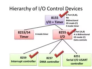
Hierarchy of I/O Control Devices. 2 Port (A,B), No Bidirectional HS mode (C) 4 mode timer. 8155 I/O + Timer. 8255 I/O. 2 Port (A,B) A is Bidirectional HS mode (C) Extra controls. 8253/54 Timer. 6 mode timer. 8259 Interrupt controller. 8237 DMA controller. 8251

E N D
Hierarchy of I/O Control Devices 2 Port (A,B), No Bidirectional HS mode (C) 4 mode timer 8155 I/O + Timer 8255 I/O 2 Port (A,B) A is Bidirectional HS mode (C) Extra controls 8253/54 Timer 6 mode timer 8259 Interrupt controller 8237 DMA controller 8251 Serial I/O USART controller
Outline • Parallel Vs Serial Communication • Characteristics of serial communication • Synchronous/A-synchronous, Simplex/Duplex, Baud rate and Error Correction • Introduction to 8251 USART controller
Data Comm: Serial Vs Parallel • Serial • Cheaper • Slower • Parallel • Faster • Data skew • Limited to small distances Data Transmission Parallel Serial Synchronous ASynchronous
Serial Communication: How ? Two basic modes of data transmission Parallel to serial Conversion Serial to parallel Conversion Sender 1 1 001001 1 1 001001 Receiver Sender 1 1 001001 1 1 001001 Receiver 10010011 Serial Transmission Parallel Transmission
Type of Serial Communication • Synchronous • Sender and receiver must synchronize • Done in hardware using phase locked loops (PLLs) • Block of data can be sent • More efficient : Less overhead than asynchronous transmission • Expensive • Asynchronous • Each byte is encoded for transmission • Start and stop bits • No need for sender and receiver synchronization
Type of Serial Communication Transmission Gaps Sender Receiver a Data Data Data Asynchronous transmission CLK Sender Receiver Data Data Data Data Data Synchronous transmission
Framing in Asynchronous • Character oriented • Each character carried start bit and stop bits • When No data are being transmitted • Receiver stay at logic 1 called mark, logic 0 is Space • Framing: • Transmission begins with one start bit (low/0) • Followed by DATA (8bit) and • Stop bits (1 or 2 bits of logic high)
Type of Serial Communication Asynchronous transmission 1 start bit 1 or 2 Stop bit Source data 1 0 0 0 1 1 1 0 LSB MSB Time Start Bit Start Bits 8 bit Data
Simplex and Duplex Transmission • Simplex • Data are transmitted in one directions • Example: CPU to printer • Duplex • Data flow in both direction • Half Duplex (Transmission goes on way at a time) • Full Duplex (Both ways simultaneously)
Rate of transmission • Rate at which bits are transmitted (BAUD) • Number of signal changes per second • Bit time: how long the Bit stay On or Off • Printer, Terminal Baud Adjustable (50-9600) • 1200Baud means: Bit stay for 1/1200=0.83ms
Error Check • Parity Check • Even parity: When odd numbers of 1 make D7=1 • Send Even number of 1 • Odd parity: When even number of 1 make D7=1 • Send Odd number of 1 • Check Sum • Used for block of data • Sum of all Bytes without carry and 2’s complements • Total Sum Result should be Zero • Cyclic Redundancy Code (CRC) • Synchronous Communication • Stream of Data can be represented by Cyclic polynomial that divided by a constant polynomial • Reminder to set Bits and Send out as check for error
Steps to be followed : Transmitting • Inform RX the start bit, end bits and parity check • Convert parallel word into stream of bits • Create a transmit word by adding start, end and proper parity bit . • Transmit one bit at a time with appropriate time delay using one data line • Time delay is determined by the speed of transmission
Steps to be followed : Receiving • Recognize bit of transmission • Receive serial bits, one bit at a time • Dismantle the start bits, end bit, parity bit, Data bits • Check the error and recognize the end of transmission • Convert serial data bit in to parallel word
Software control Asynchronous I/0using Microprocessor • 8 bit Data to be send • Steps: • Output a start bit • Convert the character to be sent in a stream of serial bits with appropriate delay • Add a parity information if needed • Output one or two stop bit
Serial Transmission in Software 8 0 8 5 Decode CSb Output Port D7 D6 D5 WRb D4 D3 D2 D1 D0
Program/Flow chat to Transmit data serially Output Bit using D0 Start Wait bit time • Set up Character bit counter • Send start bit • Rotate Next bit in D0 • Decrement the bit counter Wait bit time Is Last bit ? Get Char in ACC • Add parity if necessary • Send two stop bit Return
Serial Reception in Software 8 0 8 5 Input Port D7 D6 D5 DRb D4 D3 D2 D1 D0 Decode CSb
Flow chart to receive data serially • Set up Bit counter • Clear register to Save bits Start • Wait bit time • Read input port • Save bit Read out put port Is it bit Start? NO • Get ready to next bit • Decrement bit counter Is Last bit ? Wait half bit time Is bit Still low ? NO • Check parity if necessary • Wait for two stop bit Return
8085 Serial I/O lines • Serial Input Data (SID) • Serial Output Data (SOD) • Instruction SIM is necessary to output data • Interpretations (ACC contents) MVI A, 80 ; Set D7 in the ACC=1 RAR ;Set D6 =1 and bring carry into D7 SIM ; output D7
Data transmission Program on SOD • Transmit an ASCII Char stored in Register B MVI B ASCIIDatabyte ; get data byte in B MVI C,0BH ; set up counter for 11 bits XRA A ; reset carry to 0 NXTbit: MVI A,80H ;set D7=1 in ACC RAR ;bring Carry in D7 and set D6=1 SIM ;output D7 CALL DELAYBittime ;wait for fixed time (BWT) STC ;set Carry 1 MOV A,B ;Place ASIII car in acc RAR ; place ASCII D0 in Carry ;and shift 1 in D7 MOV B,A ;Save B DCR C JNZ NXTbit RET
Hardware control Serial I/O • Programmable chip 8251 • Requirement of HW control serial I/O • An input/output port are required for interfacing • Converts data bits in to Parallel to serial & vice versa • Data transfer to be synchronized between I/O • USART (Universal Synchronous Asynchronous Receiver and Transmitter )
UART/USART • Writing a program compatible with all different serial communication protocols is difficult and it is an inefficient use of microprocessor. • UART:Universal Asynchronous Receiver/Transmitter chip. • USART: Universal Synchronous/Asynchronous Receiver/Transmitter chip. • The microprocessor sends/receives the data to the UART in parallel, while with I/O, the UART transmits/receive data serially. • 8251 functions are integrated into standard PC interface chip.
UART / CPU interface 8251 CPU status (8 bit) xmit/ rcv data (8 bit) serial port • UART/USART • 8251 USART • 8250/16450 UART is a newer version of 8251. • 16550 is the latest version UART.