Download
1 / 48
480 likes | 886 Views
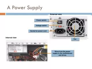
A Power Supply. External view. Power switch. Voltage switch. Socket for power cord. Internal view. Fan. Wires from the power supply to the motherboard and drives. Power Supply Wire Color Conventions. System Board Power Supply Connectors. Notch for keyed connector.

E N D
A Power Supply External view Power switch Voltage switch Socket for power cord Internal view Fan Wires from the power supply to the motherboard and drives
System Board Power Supply Connectors Notch for keyed connector A single keyed connector P8 P9 A pair of connectors
Drive Power Connectors Berg connector for floppy disk drive Molex connectors for IDE and SCSI drives
How Surge Protectors Protect Computer Equipment Electrical current flows from the outlet to the surge protector. Electrical current that is within tolerance limits for thecurrent flows into the unit and powers its components. Extra voltage is diverted to the unit’s ground or neutral wire.
BIOS TheBasic Input Output System (BIOS) is the set of instruction commands stored on a ROM chip that is used to start the most basic services of a system.
CMOS CMOS is an area of memory with battery backup that is used to store the system configuration settings that the ROM BIOS accesses during the startup sequence.
BIOS Settings BIOS settings are the low-level hardware configuration settings that are stored in the CMOS on every computer.
POST is run by the BIOS. CPU checks for BIOS. BIOS The Boot Process Power supply initializes and sends signal to CPU. Devices identified in CMOS are detected, configured, and tested. PnP devices are detected and configured. BIOS checks CMOS to locate the disk drive to boot. Hardware BIOS located, loaded, and run. BIOS information is displayed on screen and runs system tests, including a memory test.
Video Output Audio Output Problem Solution None None Power Check power cords, wall voltage, PC’s power supply. None Cursor Power Check the PC’s power supply; check for sufficient wall voltage. None DOS prompt None May be a defective speaker. One short, one long beep None Display Check for monitor power; check video cable; check display adapter. One or more short beeps DOS prompt None (normal startup beep) None. Two short beeps None or incorrect display (garbage) Display Check for monitor power; check video cable; check display adapter. Two short beeps Error code number See the next table for a list of error codes and their interpretations. Repeating short beeps Probably none Power Check the PC’s power supply; check for sufficient wall voltage. Continuous tone Probably none Power Check the PC’s power supply; check for sufficient wall voltage. One long, one short beep Probably none Motherboard Check to see that all adapters, SIMMs, and chips are seated firmly; check for proper power connections to the motherboard; use diagnostic software or hardware to further troubleshoot the motherboard. One long, two short beeps Probably none Display Check for monitor power; check video cable; check display adapter. One long, three short beeps Probably none Display Check for monitor power; check video cable; check display adapter. POST Results
POST Error Code Problem 02# Power 01## Motherboard 0104 Interrupt controller 0106 Motherboard 0151 Real-time clock or CMOS RAM 0162 CMOS checksum error 0163 Time and date (clock not updating) 164 or 0164 System memory configuration is incorrect 199 or 0199 User-indicated device list is incorrect 02## Memory 201 or 0201 Memory error (may give memory address) 0202 Memory address error 03## Keyboard 0301 Stuck key (scan code of the key may be indicated) 0302 Keyboard locked 06## Floppy disk drive or controller 0601 Floppy disk adapter failure 0602 Disk failure 17## Hard disk or adapter 1701 Drive not ready or fails tests 1704 Hard drive controller failure 1707 Track 0 failure 1714 Drive not ready 1730 - 1732 Drive adapter failure POST Error Codes
CPU The Central Processing Unit (CPU) is the integrated circuit that controls all of the system components.
Bus Types • Internal • External • System (frontside) • Data • Address • Control • Backside
CPU Performance Factors • Clock speed • Millions of Instructions Per Second (MIPS) • Amount of RAM that a processor can access • Multiprocessing • Cache • Superscalar • Superpiplining • Speculative execution • Branch prediction • Register renaming • Out-of-order completion • Dual Independent Bus (DIB) • Multimedia Extensions (MMX) • Single Instruction Multiple Data (SIMD)
A Heat Sink with Fan Fan Heat sink
A System Board Without a Daughter Board AGP slot Ports Expansion slots CPU RAM Drive interfaces
Clock Speed Clock speed refers to the number of cycles per second or frequency at which the CPU operates (e.g. 800 MHz).
Full-Size AT System Board SDRAM slots Power connector (ATX) Keyboard connector AGP slot Chipset PCI slot ZIF socket ISA slot AT socket 7 motherboard BIOS chip
Baby AT System Board REAR Keyboard connector Power connector Peripheral connectors PCI/ISA slots CPU FRONT Memory slots
LPX System Board PCI/ISA slots on riser REAR Peripheral connectors Memory slots CPU FRONT
ATX System Board REAR I/O connector CPU Power connector PCI/ISA slots Memory slots Peripheral connectors FRONT
NLX System Board Power connector Peripheral connectors FRONT PCI/ISA slots Memory slots CPU AGP port REAR
System Case Enclosure Styles Mid-size tower Micro-size tower Full-size tower Desktop
A Generic ATX System Board 25-pin parallel port connector 9-pin serial port connector USB connector PS/2 mouse and keyboard connectors PCI expansion slots AGP port CPU DIMM sockets ATX power supply connector Lithium backup battery UltraDMA EIDE connector Floppy disk drive connector
DIP Switches and Jumpers Open, or Off Closed, or On Open, or Off Closed, or On Switch or switch block Jumper block
Common Sources of System Board Problems • Computer viruses infecting the system, including the BIOS. • Loose connections between system components and the system board. • Out-of-date BIOS. • CMOS battery is not holding the BIOS information. • Damage to the CPU due to overheating or electrical damage. • Electrical shorts on the system board due to improperly seated components, power surges, or ESD. • Physical damage to the system board.
Parity 1 parity bit 8 data bits
Adding RAM to a System 20 pins 60 pins 88 pins Lock
Symptoms of Memory Problems • Computer crashes or reboots itself periodically. • Application data is corrupted. • Memory errors are displayed on the screen. • Computer appears to boot, but the screen remains blank. • Computer does not boot; POST beep codes are heard. • Newly installed memory is not recognized.