Download
1 / 13
1k likes | 2.53k Views
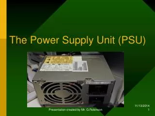
The Power Supply Unit (PSU). Function. The basic function of the PSU is to convert AC line voltage into a steady DC voltage suitable for operating a computer system. The AC input line voltage normally ranges from a minimum of 111V to 117V.

E N D
The Power Supply Unit (PSU) Presentation created by Mr. G.Robinson
Function • The basic function of the PSU is to convert AC line voltage into a steady DC voltage suitable for operating a computer system. • The AC input line voltage normally ranges from a minimum of 111V to 117V. • Typical output voltages from the PSU are normally 5V, 3.3V and 12V. The red wires produce 5V while the yellow wires produce 12V and the orange wires produce 3.3V. Presentation created by Mr. G.Robinson
PSU Black Box Presentation created by Mr. G.Robinson
Categories Of PSU • There are two broad categories that a PSU can be placed into. These are as follows: AT ATX Presentation created by Mr. G.Robinson
AT PSU Motherboard Connectors P8 P9 Presentation created by Mr. G.Robinson
ATX Motherboard Connector Presentation created by Mr. G.Robinson
Drive Connectors Drive pin-out Berge connector (3 1/2 ) Molex connector (5 1/4, CD-ROM, Hard drive ) 15-pin SATA Power connector Presentation created by Mr. G.Robinson
AT Power Switch Presentation created by Mr. G.Robinson
AT Power Switch The remote switch cable has four leads that run to it (with a fifth ground lead, to ground the power supply to the case, optional) . One pair of these (the brown and blue) run to the power cord on the back of the power supply. The other pair (black and white) run from the switch to the power supply circuitry. When the switch is on, brown connects to black, and blue connects to white, and the power supply is energized. These wires attach to spade connectors on the body of the switch. Presentation created by Mr. G.Robinson
Warning Warning: Switching the pairs of wires from one set of spade connectors to another will cause no problems as long as you exchange black with brown, and white with blue. However, if you accidentally make any other type of change, say, swapping black with blue and white with brown, the results will range from a blown fuse or circuit breaker, to smoke! Presentation created by Mr. G.Robinson
ATX Soft Power Switch • Starting with the ATX/NLX form factor, the way the power switch works has been changed altogether. Instead of using a physical toggle switch connected to the power supply, on modern systems the power switch is electronic. It connects to the motherboard, much the way that the reset switch does, using a feature called soft power. So on an ATX system, when you press the power switch, you aren't really turning on the power supply; it is more like sending a "request" to the motherboard to turn the system on. As a result, the switch is a simple affair and the wires carry only low-current DC power, removing the potential risks inherent in the AT-style switch (well, risks if you tamper with the PC when it is plugged in anyway!) Presentation created by Mr. G.Robinson
The Power_Good Signal • The power_good signal (sometimes called Power_OK or POK) is a +5V signal ( with variation from +3.0 through +6.0V generally being considered acceptable) generated in the power supply when it has passed its internal self test and the output stabilized. The power supply sends this signal to the motherboard, where it is received by the processor timer chip, which controls the reset line to the processor. In the absence of the power_good signal the timer chips continually reset the processor, which prevents the system from running under bad or unstable power conditions. Presentation created by Mr. G.Robinson
Troubleshooting Guide Presentation created by Mr. G.Robinson