Download
1 / 16
160 likes | 268 Views
FIGURE 25–1 A capless system from a Ford Flex does not use a replaceable cap; instead, it is spring-loaded closed. FIGURE 25–2 A charcoal canister can be located under the hood or underneath the vehicle.

E N D
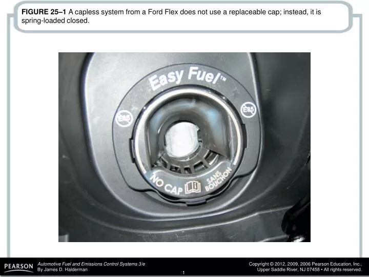
FIGURE 25–1 A capless system from a Ford Flex does not use a replaceable cap; instead, it is spring-loaded closed.
FIGURE 25–2 A charcoal canister can be located under the hood or underneath the vehicle.
FIGURE 25–3 The EVAP system includes all of the lines, hoses, and valves, plus the charcoal canister.
FIGURE 25–4 A typical EVAP system. Note that when the computer turns on the canister purge solenoid valve, manifold vacuum draws any stored vapors from the canister into the engine. Manifold vacuum also is applied to the pressure control valve. When this valve opens, fumes from the fuel tank are drawn into the charcoal canister and eventually into the engine. When the solenoid valve is turned off (or the engine stops and there is no manifold vacuum), the pressure control valve is spring-loaded shut to keep vapors inside the fuel tank from escaping to the atmosphere.
FIGURE 25–5 An enhanced EVAP system is able to perform system and leak detection diagnosis.
FIGURE 25–6 A leak detection pump (LDP) used on some Chrysler and other vehicles to pressurize (slightly) the fuel system to check for leaks.
FIGURE 25–7 A restricted fuel fill pipe shown on vehicle with the interior removed.
FIGURE 25–8 Some vehicles will display a message if an evaporative control system leak is detected that could be the result of a loose gas cap.
FIGURE 25–9 To test for a leak, this tester was set to the 0.020-inch hole and turned on. The ball rose in the scale on the left, and the red arrow was moved to that location. If when testing the system for leaks the ball rises higher than the arrow, then the leak is larger than 0.02 inch. If the ball does not rise to the level of the arrow, the leak is smaller than 0.020 inch.
FIGURE 25–10 This unit is applying smoke to the fuel tank through an adapter, and the leak was easily found to be the gas cap seal.
FIGURE 25–11 An emission tester that uses nitrogen to pressurize the fuel system.
FIGURE 25–12 The fuel tank pressure sensor (black unit with three wires) looks like a MAP sensor and is usually located on top of the fuel pump module (white unit).
FIGURE 25–13 A tank car was cleaned using steam, and then both the bottom drain and the top vent were closed. The next day, the tank had collapsed because of the air pressure difference when the inside cooled. The higher outside air pressure caused the tank to collapse.
FIGURE 25–14 This Toyota cap warns that the check engine light will come on if not tightened until one click.
FIGURE 25–15 To easily check the fuel tank pressure sensor, remove the cap, and the sensor should read about 1.7 volts.
FIGURE 25–16 The fuel level must be above 15% and below 85% before the EVAP monitor will run on most vehicles.