Fast Communication for Multi – Core SOPC
350 likes | 530 Views
Fast Communication for Multi – Core SOPC. Technion – Israel Institute of Technology Department of Electrical Engineering High Speed Digital Systems Lab. Spring 2007. End Project Presentation. Supervisor: Evgeny Fiksman Performed by: Moshe Bino Alex Tikh. One year project.

Fast Communication for Multi – Core SOPC
E N D
Presentation Transcript
FastCommunication for Multi – Core SOPC Technion – Israel Institute of Technology Department of Electrical Engineering High Speed Digital Systems Lab Spring 2007 End Project Presentation Supervisor: Evgeny Fiksman Performed by: Moshe Bino Alex Tikh One year project
Table of Content Introduction Hardware Design Software Design Debug Process Results Future Research Table of Content
Table of Content Introduction Hardware Design Software Design Debug Process Results Future Research Table of Content
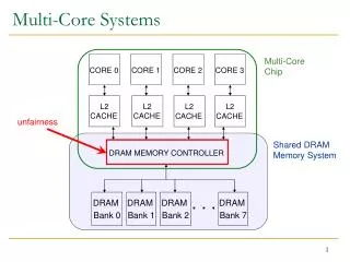
Problem statement Single CPU is reaching its technological limits, e.g. heat dissipation and cost/power ratio. Thus parallel computing evolved, utilizing multi core processor paradigm. Three major inter-communication techniques are: Shared memory Remote procedure calls. Message passing – (MPI) Introduction
Project Overview • Mesh topology NoC • Routing nodes • Leaf processor cores • MPI logically defines clusters • Comm • Rank • Cores amount is limited only by chip resources Introduction
The following components are to be implemented: Quad core system. NoC router (4 ports) and infrastructure for fast communication in multi-core system. Chosen MPI functions written in C. Software application demonstrating the advantages of a parallel system (written in C). Project goals Introduction
Block diagram • Multi – core IP’s • Bi - directional link FSL • Local memory • Main core connected to I/O • Multi - clock domain • System on programmable chip implemented on FPGA Introduction
Constrains: FPGA (V2P) maximum clock frequency 400MHz. MicroBlaze (MB) core maximum frequency 100MHz. Router maximum frequency 200MHz Processors Memory size 64kbyte. (code + data). Processor to FSL access time - 3 clock cycles. Maximum FSL buffer depth is 128 - equals 0.5kbyte. Interrupt handle time - 20 clock cycles (no interrupts nesting). Measurement system: Router works at 100MHz frequency. MB works at 25MHz frequency. FSL depth is 64 word - 0.25kbyte Router is designed for relatively small messages – max. 1kbyte due to processors & FPGA chip memory size. System specifications Introduction
Table of Content Introduction Hardware Design Software Design Debug Process Results Future Research Table of Content
Router Implementation Hardware Design
CROSS – BAR • Two main units: • Permission Unit • Port FSM • Time limited • Round Robin arbiter • Port to Port & broadcasting • Smart Connectivity • R – R • R - Core • Modular design Hardware Design
Table of Content Introduction Hardware Design Software Design Debug Process Results Future Research Table of Content
MicroBlaze#2 Application Network Data Physical System software Layers • Application • MPI functions interface • Network • hardware independent implementation • Data • relies on message structure • Physical • designed for FSL bus MicroBlaze#1 MPI Application Network Data Physical Design modularity in hardware and software Software design
MPI Functions set Software design
Table of Content Introduction Hardware Design Software Design Debug Process Results Future Research Table of Content
Debug – Simulation • The Test Bench write messages to the FSL pipe (MB output side) and reads messages from the pipe (MB input side). • Signals can also be viewed in ModelSim Debug Process
Debug process – Real time • Software debug using 2 MB system. • Debug mainly done using printf function for plotting results to monitor trough UART. • Hardware debug was using chip scope application and LEDs for indication Debug Process
Table of Content Introduction Hardware Design Software Design Debug Process Results Future Research Table of Content
Example applicationMatrix - Vector multiplication Results Typical example of highly parallel application. Root processor broadcasts Vector. Selected Matrix Row sent by root to each processor. Each processor computes and returns its result. Computed results are combined into a vector by root processor.
Example applicationMatrix - Vector multiplication Router MPI MPI MPI MPI Results
Matrix - Vector multiplication - results • For simple operations single processor is preferred Results * Time = ticks/clk frequency
Matrix - Vector multiplication - results • When the operation takes more time than the send and receive time the router becomes efficient Results
Router statistics • Transfer time theoretical limit is 8 clock cycle time • The limit is calculated from: • 3 clks for putfsl. • 2 clks for router read & write. • 3 clks for getfsl • total = 8 clks Results
Router statistics • Bcast takes more time then send. • The slope value (8) comes from transfer limit time. Results
Router statistics Results
Table of Content Introduction Hardware Design Software Design Debug Process Results Future Research Table of Content
Future Directions • Improve router performance ~400Mhz • Expand network to more than 4 processors Future research
Message payload • The Header consist of the fields: • The Tail consist of the fields: *Empty fields where left to allow network and functionality extensions. Introduction
Example 1 • At each time slot part of the message is send to it’s destination as long as the destination port is not busy. • When Port is busy the next requesting port is service (no delay). Hardware Design
Example 2 • If one port has no data (port 2) other ports are serviced by order. Hardware Design
Example 3 • Handling BCAST command and port arbitrating while 2 ports has the same destination. Hardware Design
MPI_Send: composes header and tail, and sends it with the message (body) Sending the message Software Design
Receiving the message Interrupt Vector: receives incoming messages, and stores them in suitable linked list Software Design
Return received message MPI_Recv: message details received from user. Looks for this message in linked list of already received messages Software Design