Download
1 / 7
70 likes | 92 Views
Explore DSP processing in signal transmission using DAC, ADC, RF modules, and practice modulation and recovery experiments.

E N D
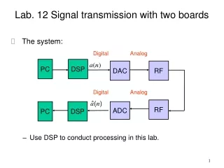
Lab. 12 Signal transmission with two boards • The system: • Use DSP to conduct processing in this lab. Digital Analog PC DSP a(n) DAC RF Digital Analog RF PC DSP ADC
Tx/rx experiments: • Use DSP to generate a sinusoidal signal, and conduct up-conversion. Transmit the signal to the receiver in another board. • Use cable for connection. • DAC/ADC rate: 1Mps • Carrier: 2.31GHz Analog Digital DSP FPGA DAC RF EMIF DSP FPGA ADC RF
Practice 1: • Use DSP to generate a sinusoidal signal and transmit it through the RF module. • Use another board as the receiver and observe the received time-domain signal. • Observe its spectrum. • Why do you have two sinusoidal in the received signal?
Practice 2: • Repeat the experiment in Practice 1. • Figure out a way in the received to recover the transmit signal.
Digital modulation system: Digital Digital Analog PC DSP a(n) DAC/RF Filter Map Digital filter (SRRC) Digital Digital Analog PC DSP ADC/RF Dem. Filter Digital filter (SRRC) Implemented with DSP
Tx experiments: • Use DSP to generate a bit sequence, and conduct modulation and pulse shaping. • Transmit the signal to the receiver in another board. • DAC/ADC rate: 1Mps • Carrier: 2.31GHz Analog Digital DSP FPGA DAC RF EMIF DSP FPGA ADC RF
Practice 3: • Use DSP to generate a bit sequence, conduct QPSK mapping, and the pulse shaping. • Then, transmit the signal to another board with a cable. • Record the received signal and transmit it to PC and observe the signal constellation.