Download
1 / 17
190 likes | 462 Views
Learn about the operation and construction of synchronous machines used in power generation and as motors. Discover the different types of synchronous generators and motors, including high-speed and low-speed machines. Explore the principles of synchronous generators and their applications in various industries.

E N D
Chapter 5. Synchronous Machines
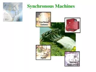
Introduction • Unlike induction machines, the rotating air gap field and the rotor in the synchronous machine rotate at the same speed, called the synchronous speed. • Synchronous machines are used primarily as generators of electrical power, called synchronous generators or alternators. • They are usually large machines generating electrical power at hydro, nuclear, or thermal power stations. • Synchronous generators with power ratings of several hundred MVA are quite common in generating stations. • Synchronous generators are the primary energy conversion devices of the world’s electric power systems today.
Introduction • Like most rotating machines, a synchronous machine can also operate as both a generator and motor. • In large sizes synchronous motors are used for pumps in generating stations. • In small sizes they are used in electric clocks, timers, and so forth where constant speed is desired. • A linear version of the synchronous motor (LSM) is being considered for high-speed transportation systems of the future.
Introduction • A synchronous machine is doubly excited machine. • The rotor poles are excited by a dc machine and its stator windings are connected to the ac supply. • The air gap flux is therefore the resultant of the fluxes due to both rotor current and stator current. • If the synchronous motor is not loaded but is simply floating on the ac supply system, it will be thus behave as a variable inductor or capacitor as its rotor field current is changed. This machine is called synchronous condenser. • It may be used in power transmission systems to regulate line voltage.
Introduction Synchronous Machines: •Synchronous Generators: A primary source of electrical energy. •Synchronous Motors: Used as motors as well as power factor compensators (synchronous condensers). Asynchronous (Induction) Machines: •Induction Motors: Most widely used electrical motors in both domestic and industrial applications. •Induction Generators: Due to lack of a separate field excitation, these machines are rarely used as generators.
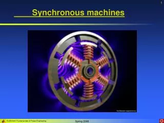
Introduction View of a two-pole round rotor generator and exciter.
Construction • The stator of three-phase synchronous machine has a three-phase distributed winding similar to that of the three-phase induction machine. • The stator winding, which is connected to the ac supply, is sometimes called the armature winding. It is designed for high voltage and current. • The rotor has a winding called the field winding, which carries direct current. • The field winding on the rotating structure is normally fed from an external dc source through slip rings and brushes.
Synchronous machine can be broadly divided into two groups as follows: High-speed machines with cylindrical (or non-salient pole) rotors. Low-speed machines with salient pole rotors. Non-salient pole generator • high speed (2 - 4 poles) • large power (100 - 400 MVA) • steam and nuclear power plants Salient pole generator • small and mid-size power (0-100MVA) • small motors for electrical clocks and other domestic devices • mid size generators for emergency power supply • mid size motors for pumps and ship propulsion • large size generators in hydro-electric power plants Construction
The stator is a ring shaped laminated iron-core with slots. Three phase windings are placed in the slots. Round solid iron rotor with slots. A single winding is placed in the slots. DC current is supplied through slip rings. Round Rotor Machine
The stator has a laminated iron-core with slots and three phase windings placed in the slots. The rotor has salient poles excited by dc current. DC current is supplied to the rotor through slip-rings and brushes. Salient Rotor Machine
Synchronous Generator Principle of Operation 1) From an external source, the field winding is supplied with a DC current -> excitation. 2) Rotor (field) winding is mechanically turned (rotated) at synchronous speed. 3) The rotating magnetic field produced by the field current induces voltages in the outer stator (armature) winding. The frequency of these voltages is in synchronism with the rotor speed.
Synchronous Generator • When the field current If flows through the rotor field winding, it establishes a sinusoidally distributed flux in the air gap. • If the rotor is now rotated by the prime mover (which can be a turbine or diesel engine or dc motor or induction motor), a revolving field is produced by the excitation current If. • The rotating flux so produced will change the flux linkage of the armature windings and will induce voltages in these stator windings. • They are called excitation voltages Ef.
Synchronous Generator • The rotor frequency and speed of the induced voltage are related by • The excitation voltage in rms is p = no of poles n = rotor speed (rpm) f = flux/ poles due to If N = no of turns in each phase Kw = winding factor
Ff f Fr r Ef a Fa Ia Excitation voltage Excitation current Open Circuit characteristic of Synchronous Machine ( at constant speed) f – flux due to If – due to DC excitation a – flux due to Ia – due to armature/stator current, assume lagging current r = f + a – resultant air gap =msinwt E= - Nd/dt f Space Phasor Diagram of Synchronous Machine
Parallel Operation Generators are rarely used in isolated situations. More commonly, generators are used in parallel, often massively in parallel, such as in the power grid. The following steps must be adhered when adding a generator to an existing power grid ( infinite bus bar): 1) RMS line voltages of the two generators must be the same. 2) Phase sequence must be the same. 3) Phase angles of the corresponding phases must be the same. 4) Frequency must be the same. This can be checked by an instrument known as synchroscope meter