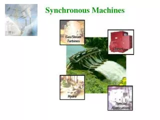
Synchronous machines
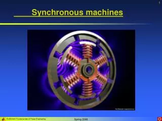
Synchronous machines. Construction of synchronous machines. Synchronous machines are AC machines that have a field circuit supplied by an external DC source.

Synchronous machines
E N D
Presentation Transcript
Construction of synchronous machines Synchronous machines are AC machines that have a field circuit supplied by an external DC source. In a synchronous generator, a DC current is applied to the rotor winding producing a rotor magnetic field. The rotor is then turned by external means producing a rotating magnetic field, which induces a 3-phase voltage within the stator winding. In a synchronous motor, a 3-phase set of stator currents produces a rotating magnetic field causing the rotor magnetic field to align with it. The rotor magnetic field is produced by a DC current applied to the rotor winding. Field windings are the windings producing the main magnetic field (rotor windings for synchronous machines); armature windings are the windings where the main voltage is induced (stator windings for synchronous machines).
Construction of synchronous machines The rotor of a synchronous machine is a large electromagnet. The magnetic poles can be either salient (sticking out of rotor surface) or non-salient construction. Non-salient-pole rotor: usually two- and four-pole rotors. Salient-pole rotor: four and more poles. Rotors are made laminated to reduce eddy current losses.
Construction of synchronous machines A synchronous rotor with 8 salient poles Salient pole without field windings – observe laminations Salient pole with field windings
Construction of synchronous machines Two common approaches are used to supply a DC current to the field circuits on the rotating rotor: • Supply the DC power from an external DC source to the rotor by means of slip rings and brushes; • Supply the DC power from a special DC power source mounted directly on the shaft of the machine. Slip rings are metal rings completely encircling the shaft of a machine but insulated from it. One end of a DC rotor winding is connected to each of the two slip rings on the machine’s shaft. Graphite-like carbon brushes connected to DC terminals ride on each slip ring supplying DC voltage to field windings regardless the position or speed of the rotor.
Construction of synchronous machines Slip rings Brush
Construction of synchronous machines Slip rings and brushes have certain disadvantages: increased friction and wear (therefore, needed maintenance), brush voltage drop can introduce significant power losses. Still this approach is used in most small synchronous machines. On large generators and motors, brushless exciters are used. A brushless exciter is a small AC generator whose field circuits are mounted on the stator and armature circuits are mounted on the rotor shaft. The exciter generator’s 3-phase output is rectified to DC by a 3-phase rectifier (mounted on the shaft) and fed into the main DC field circuit. It is possible to adjust the field current on the main machine by controlling the small DC field current of the exciter generator (located on the stator). Since no mechanical contact occurs between the rotor and the stator, exciters of this type require much less maintenance.
Construction of synchronous machines A brushless exciter: a low 3-phase current is rectified and used to supply the field circuit of the exciter (located on the stator). The output of the exciter’s armature circuit (on the rotor) is rectified and used as the field current of the main machine.
Construction of synchronous machines To make the excitation of a generator completely independent of any external power source, a small pilot exciter is often added to the circuit. The pilot exciter is an AC generator with a permanent magnet mounted on the rotor shaft and a 3-phase winding on the stator producing the power for the field circuit of the exciter.
Construction of synchronous machines A rotor of large synchronous machine with a brushless exciter mounted on the same shaft. Many synchronous generators having brushless exciters also include slip rings and brushes to provide emergency source of the field DC current.
Construction of synchronous machines A large synchronous machine with the exciter and salient poles.
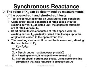
Rotation speed of synchronous generator By the definition, synchronous generators produce electricity whose frequency is synchronized with the mechanical rotational speed. (7.11.1) Where fe is the electrical frequency, Hz; nm is mechanical speed of magnetic field (rotor speed for synchronous machine), rpm; P is the number of poles. Steam turbines are most efficient when rotating at high speed; therefore, to generate 60 Hz, they are usually rotating at 3600 rpm and turn 2-pole generators. Water turbines are most efficient when rotating at low speeds (200-300 rpm); therefore, they usually turn generators with many poles.
Internal generated voltage of a synchronous generator The magnitude of internal generated voltage induced in a given stator is where K is a constant representing the construction of the machine, is flux in it and is its rotation speed. Since flux in the machine depends on the field current through it, the internal generated voltage is a function of the rotor field current. Magnetization curve (open-circuit characteristic) of a synchronous machine
Equivalent circuit of a synchronous generator • The internally generated voltage in a single phase of a synchronous machine EA is not usually the voltage appearing at its terminals. It equals to the output voltage V only when there is no armature current in the machine. The reasons that the armature voltage EA is not equal to the output voltage V are: • Distortion of the air-gap magnetic field caused by the current flowing in the stator (armature reaction); • Self-inductance of the armature coils; • Resistance of the armature coils; • Effect of salient-pole rotor shapes.
Equivalent circuit of a synchronous generator Armature reaction (the largest effect): When the rotor of a synchronous generator is spinning, a voltage EA is induced in its stator. When a load is connected, a current starts flowing creating a magnetic field in machine’s stator. This stator magnetic field BS adds to the rotor (main) magnetic field BR affecting the total magnetic field and, therefore, the phase voltage. Lagging load
Equivalent circuit of a synchronous generator Assuming that the generator is connected to a lagging load, the load current IA will create a stator magnetic field BS, which will produce the armature reaction voltage Estat. Therefore, the phase voltage will be (7.16.1) The net magnetic flux will be (7.16.2) Rotor field Stator field Note that the directions of the net magnetic flux and the phase voltage are the same.
Equivalent circuit of a synchronous generator Assuming that the load reactance is X, the armature reaction voltage is (7.17.1) The phase voltage is then (7.17.2) Armature reactance can be modeled by the following circuit… However, in addition to armature reactance effect, the stator coil has a self-inductance LA (XA is the corresponding reactance) and the stator has resistance RA. The phase voltage is thus (7.17.3)
Equivalent circuit of a synchronous generator Often, armature reactance and self-inductance are combined into the synchronous reactance of the machine: (7.18.1) Therefore, the phase voltage is (7.18.2) The equivalent circuit of a 3-phase synchronous generator is shown. The adjustable resistor Radj controls the field current and, therefore, the rotor magnetic field.
Equivalent circuit of a synchronous generator A synchronous generator can be Y- or -connected: The terminal voltage will be (7.19.1) (7.19.2)
Equivalent circuit of a synchronous generator Note: the discussion above assumed a balanced load on the generator! Since – for balanced loads – the three phases of a synchronous generator are identical except for phase angles, per-phase equivalent circuits are often used.
Phasor diagram of a synchronous generator Since the voltages in a synchronous generator are AC voltages, they are usually expressed as phasors. A vector plot of voltages and currents within one phase is called a phasor diagram. A phasor diagram of a synchronous generator with a unity power factor (resistive load) Lagging power factor (inductive load): a larger than for leading PF internal generated voltage EA is needed to form the same phase voltage. Leading power factor (capacitive load). For a given field current and magnitude of load current, the terminal voltage is lower for lagging loads and higher for leading loads.
Power and torque in synchronous generators A synchronous generator needs to be connected to a prime mover whose speed is reasonably constant (to ensure constant frequency of the generated voltage) for various loads. The applied mechanical power (7.22.1) is partially converted to electricity (7.22.2) Where is the angle between EA and IA. The power-flow diagram of a synchronous generator.
Power and torque in synchronous generators The real output power of the synchronous generator is (7.23.1) The reactive output power of the synchronous generator is (7.23.2) Recall that the power factor angle is the angle between V and IA and not the angle between VT and IL. In real synchronous machines of any size, the armature resistance RA << XSand, therefore, the armature resistance can be ignored. Thus, a simplified phasor diagram indicates that (7.23.3)
Power and torque in synchronous generators Then the real output power of the synchronous generator can be approximated as (7.24.1) We observe that electrical losses are assumed to be zero since the resistance is neglected. Therefore: (7.24.2) Here is the torque angle of the machine– the angle between V and EA. The maximum power can be supplied by the generator when = 900: (7.24.3)
Power and torque in synchronous generators The maximum power specified by (7.24.3) is called the static stability limit of the generator. Normally, real generators do not approach this limit: full-load torque angles are usually between 150 and 200. The induced torque is (7.25.1) Notice that the torque angle is also the angle between the rotor magnetic field BR and the net magnetic field Bnet. Alternatively, the induced torque is (7.25.2)
Parallel operation of synchronous generators • Most of synchronous generators are operating in parallel with other synchronous generators to supply power to the same power system. Obvious advantages of this arrangement are: • Several generators can supply a bigger load; • A failure of a single generator does not result in a total power loss to the load increasing reliability of the power system; • Individual generators may be removed from the power system for maintenance without shutting down the load; • A single generator not operating at near full load might be quite inefficient. While having several generators in parallel, it is possible to turn off some of them when operating the rest at near full-load condition.
Conditions required for paralleling A diagram shows that Generator 2 (oncoming generator) will be connected in parallel when the switch S1 is closed. However, closing the switch at an arbitrary momentcan severely damage both generators! • If voltages are not exactly the same in both lines (i.e. in a and a’, b and b’ etc.), a very large current will flow when the switch is closed. Therefore, to avoid this, voltages coming from both generators must be exactly the same. Therefore, the following conditions must be met: • The rms line voltages of the two generators must be equal. • The two generators must have the same phase sequence. • The phase angles of two a phases must be equal. • The frequency of the oncoming generator must be slightly higher than the frequency of the running system.
Conditions required for paralleling If the phase sequences are different, then even if one pair of voltages (phases a) are in phase, the other two pairs will be 1200 out of phase creating huge currents in these phases. If the frequencies of the generators are different, a large power transient may occur until the generators stabilize at a common frequency. The frequencies of two machines must be very close to each other but not exactly equal. If frequencies differ by a small amount, the phase angles of the oncoming generator will change slowly with respect to the phase angles of the running system. If the angles between the voltages can be observed, it is possible to close the switch S1 when the machines are in phase.
General procedure for paralleling generators • When connecting the generator G2 to the running system, the following steps should be taken: • Adjust the field current of the oncoming generator to make its terminal voltage equal to the line voltage of the system (use a voltmeter). • Compare the phase sequences of the oncoming generator and the running system. This can be done by different ways: • Connect a small induction motor to the terminals of the oncoming generator and then to the terminals of the running system. If the motor rotates in the same direction, the phase sequence is the same; 2) Connect three light bulbs across the open terminals of the switch. As the phase changes between the two generators, light bulbs get brighter (large phase difference) or dimmer (small phase difference). If all three bulbs get bright and dark together, both generators have the same phase sequences.
General procedure for paralleling generators If phase sequences are different, two of the conductors on the oncoming generator must be reversed. 3. The frequency of the oncoming generator is adjusted to be slightly higher than the system’s frequency. 4. Turn on the switch connecting G2 to the system when phase angles are equal. The simplest way to determine the moment when two generators are in phase is by observing the same three light bulbs. When all three lights go out, the voltage across them is zero and, therefore, machines are in phase. A more accurate way is to use a synchroscope – a meter measuring the difference in phase angles between two a phases. However, a synchroscope does not check the phase sequence since it only measures the phase difference in one phase. The whole process is usually automated…
Operation of generators in parallel with large power systems Often, when a synchronous generator is added to a power system, that system is so large that one additional generator does not cause observable changes to the system. A concept of an infinite bus is used to characterize such power systems. An infinite bus is a power system that is so large that its voltage and frequency do not vary regardless of how much real and reactive power is drawn from or supplied to it. The power-frequency and reactive power-voltage characteristics are:
Synchronous motors The field current IF of the motor produces a steady-state rotor magnetic field BR. A 3-phase set of voltages applied to the stator produces a 3-phase current flow in the windings. A 3-phase set of currents in an armature winding produces a uniform rotating magnetic field Bs. Two magnetic fields are present in the machine, and the rotor field tends to align with the stator magnetic field. Since the stator magnetic field is rotating, the rotor magnetic field will try to catch up pulling the rotor. The larger the angle between two magnetic fields (up to a certain maximum), the greater the torque on the rotor of the machine.
Synchronous motor equivalent circuit A synchronous motor has the same equivalent circuit as synchronous generator, except that the direction of power flow (and the direction of IA) is reversed. Per-phase circuit is shown: A change in direction of IA changes the Kirchhoff’s voltage law equation: (7.69.1) Therefore, the internal generated voltage is (7.69.2) We observe that this is exactly the same equation as the equation for the generator, except that the sign on the current terms is reversed.
Synchronous motor vs. synchronous generator Let us suppose that a phasor diagram of synchronous generator is shown. BR produces EA, Bnet produces V, and BS produces Estat = -jXSIA. The rotation on both diagrams is counterclockwise and the induced torque is (7.70.1) clockwise, opposing the direction of rotation. In other words, the induced torque in generators is a counter-torque that opposes the rotation caused by external torque. If the prime mover loses power, the rotor will slow down and the rotor field BR will fall behind the magnetic field in the machine Bnet. Therefore, the operation of the machine changes…
Synchronous motor vs. synchronous generator The induced torque becomes counter-clockwise, being now in the direction of rotation. The machine starts acting as a motor. The increasing torque angle results in an increasing torque in the direction of rotation until it equals to the load torque. At this point, the machine operates at steady state and synchronous speed but as a motor. Notice that, since the direction of IA is changed between the generator and motor actions, the polarity of stator voltage (-jXSIA) also changes. In a summary: in a generator, EA lies ahead of V, while in a motor, EA lies behind V.
Steady-state operation of motor: Torque-speed curve Usually, synchronous motors are connected to large power systems (infinite bus); therefore, their terminal voltage and system frequency are constant regardless the motor load. Since the motor speed is locked to the electrical frequency, the speed should be constant regardless the load. The steady-state speed of the motor is constant from no-load to the maximum torque that motor can supply (pullout torque). Therefore, the speed regulation of synchronous motor is 0%. The induced torque is (7.72.1) or (7.72.2)
Steady-state operation of motor: Torque-speed curve The maximum pullout torque occurs when = 900: (7.73.1) Normal full-load torques are much less than that (usually, about 3 times smaller). When the torque on the shaft of a synchronous motor exceeds the pullout torque, the rotor can no longer remain locked to the stator and net magnetic fields. It starts to slip behind them. As the motor slows down, the stator magnetic field “laps” it repeatedly, and the direction of the induced torque in the rotor reverses with each pass. As a result, huge torque surges of alternating direction cause the motor vibrate severely. The loss of synchronization after the pullout torque is exceeded is known as slipping poles.
Starting synchronous motors Consider a 60 Hz synchronous motor. When the power is applied to the stator windings, the rotor (and, therefore its magnetic field BR) is stationary. The stator magnetic field BS starts sweeping around the motor at synchronous speed. Note that the induced torque on the shaft (7.84.1) is zero at t = 0 since both magnetic fields are aligned. At t = 1/240 s the rotor has barely moved but the stator magnetic field BS has rotated by 900. Therefore, the torque on the shaft is non-zero and counter-clockwise.
Starting synchronous motors At t = 1/120 s the rotor and stator magnetic fields point in opposite directions, and the induced torque on the shaft is zero again. At t = 3/240 s the stator magnetic fields point to the right, and the induced torque on the shaft is non-zero but clockwise. Finally, at t = 1/60 s the rotor and stator magnetic fields are aligned again, and the induced torque on the shaft is zero. During one electrical cycle, the torque was counter-clockwise and then clockwise, and the average torque is zero. The motor will vibrate heavily and finally overheats!
Starting synchronous motors • Three basic approaches can be used to safely start a synchronous motor: • Reduce the speed of the stator magnetic field to a low enough value that the rotor can accelerate and two magnetic fields lock in during one half-cycle of field rotation. This can be achieved by reducing the frequency of the applied electric power (which used to be difficult but can be done now). • Use an external prime mover to accelerate the synchronous motor up to synchronous speed, go through the paralleling procedure, and bring the machine on the line as a generator. Next, turning off the prime mover will make the synchronous machine a motor. • Use damper windings or amortisseur windings – the most popular.
Motor starting by amortisseur or damper windings Amortisseur (damper) windings are special bars laid into notches carved in the rotor face and then shorted out on each end by a large shorting ring.
Motor starting by amortisseur or damper windings • We observe that the torque is either counter-clockwise or zero, but it is always unidirectional. Since the net torque is nonzero, the motor will speed up. • However, the rotor will never reach the synchronous speed! If a rotor was running at the synchronous speed, the speed of stator magnetic field BS would be the same as the speed of the rotor and, therefore, no relative motion between the rotor and the stator magnetic field. If there is no relative motion, no voltage is induced and, therefore, the torque will be zero. • Instead, when the rotor’s speed is close to synchronous, the regular field current can be turned on and the motor will operate normally. In real machines, field circuit are shorted during starting. Therefore, if a machine has damper winding: • Disconnect the field windings from their DC power source and short them out; • Apply a 3-phase voltage to the stator and let the rotor to accelerate up to near-synchronous speed. The motor should have no load on its shaft to enable motor speed to approach the synchronous speed as closely as possible; • Connect the DC field circuit to its power source: the motor will lock at synchronous speed and loads may be added to the shaft.