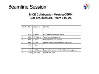
Beamline Session
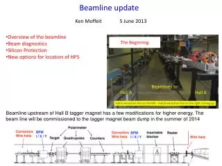
Beamline Session. MICE Collaboration Meeting CERN Tues am. 30/03/04. Room 6-02-24. MICE Target Status. Chris Booth 30 th March 2004. The challenge. ISIS beam shrinks from 73 mm to 55 mm radius during acceleration Target must remain outside beam until 2 ms before extraction

Beamline Session
E N D
Presentation Transcript
Beamline Session MICE Collaboration Meeting CERNTues am. 30/03/04. Room 6-02-24.
MICE TargetStatus Chris Booth 30th March 2004
The challenge • ISIS beam shrinks from 73 mm to 55 mm radius during acceleration • Target must remain outside beam until 2 ms before extraction • Then enters 5mm (into halo) • Must be out of beam by next injection • Beam cycle length 20 ms • Target operation “on demand”, 1 to 10 (or 50) Hz
The challenge (continued) • Operation in vacuum • No lubricated bearings • No convective cooling • Operation in radiation environment • Must cause minimal vibration • Must be completely reliable and maintenance-free
Basic drive specifications • Travel >25 mm • Peak acceleration (min.) ~1 mm ms-2 =1000 ms-2 =100 g • Rep. rate • On demand 1 Hz 10 Hz ( 50Hz?) • (Machine cycle length 20 ms)
Ideal target motion • Infinite acceleration!
Diaphragm spring N S Array of coils Current design: Moving magnet Section Target
Advantages • Lower mass – light moving magnet (sintered neodymium-iron-boron) • Stationary windings – more power, many cooling options • Larger travel possible Disadvantages • Multiple coils • More sophisticated power supply & commutator required • Phase and amplitude control required
Control ideas • 2 levels • Rapid hardware position feedback to ensure 1-pulse stability. • Pulse-to-pulse monitoring (software) to provide slow adjustments. Position monitoring requirements • For monitoring - Precision 0.2 mm, sampled every 0.1 ms • For drive phase control - Precision ~ mm, timing ~ 0.2 ms ?
Position monitoring method? • LVDT (Linear Variable Differential Transformer) • Good precision, but not fast enough • Optical encoder • Excellent precision, probably not fast enough, not radiation hard • Capacitive sensor? • Precision, stability, speed not yet clear! • Magnetic sensor? • Is electronics rad hard?
Next steps • Continue design studies with EEE • Build prototype magnet/coil system • Design/make/acquire diaphragm springs with sufficient travel • Develop fast position sensing • Interface to power supply/driver • Implement 2-stage feedback • Test and characterise
Timetable?? • First prototype Summer 04 • Develop control Autumn 04 • System tests Winter 04-05 • Cooling, stability tests Spring-Summer 05 • Rad-hard components Spring-Summer 05 • Interfaces with ISIS Spring-Summer 05 • Implement improvements Summer 05 • Final device construct/test Autumn-Winter 05 • Install Winter-Spring 06
MICE Target Development Chris Booth & team • Proposed activities April – August: • Any useful inputs from the Collaboration? As per timeline. Alternative Position Sensing Ideas…?
MICE Target Source Calculations Tom Roberts Illinois Institute of Technology March 30, 2004
Model of Target and ISIS Beam * Estimate of: (beam density at target)/(average beam density)
Outline of Computation • Select beamline tune, determine an enclosing target acceptance (Pmin, Pmax, x’min, x’max, y’min,y’max) • Use LAHET, MARS, and g4beamline (Geant4) to determine pi+ that enter the target acceptance per proton on target • Use g4beamline to generate 20M pi+ into the target acceptance, and determine how may good mu+ they produce. • Model the ISIS beam and target to determine the rate of protons on target. • Put the above values together to determine the absolute rate of good-mu+/millisecond.
Target Particle Production Particles into acceptance per millisecond of good target.
Target Source/Physics Work Tom Roberts & team • Proposed activities April – August: • Any inputs requested from Collaboration? Only nominally minor refinements... None suggested.
Particle ID in the MICE Beamline Paul Soler, Kenny Walaron University of Glasgow and Rutherford Appleton Laboratory MICE Collaboration Meeting 30 March 2004.
Aims • Carry out particle identification in the MICE beamline using scintillation detectors. • Use dE/dx signature to differentiate between protons and pions/muons at different positions along beamline: e.g. before Q1 and at input and output of solenoid. • Use PID information to qualify and monitor beamline simulation. • Caveat: More a statement of intentions than results.
Scintillator layout • Would aim to have as little segmentation as possible • If rate proves to be a problem, perform segmentation, with smaller segmentation in centre. For example: Scintillator Waveguides Waveguides PMTs PMTs • Double sided readout allows to measure energy, independent of position of particle along scintillator.
GEANT4 Beamline Simulation • MICE beam simulation prepared in GEANT4 (see Tom Roberts presentation 24/9/03 and 14/1/04) showed differences between G4 and other simulations: 57% difference! Need to validate simulations by measuring rates, profiles and particle ID along beamline.
MICE Beamline New beamline layout (Tilley/Roberts) PID scintillators? Q1 Q2 Q3 TOF1 TOF1 Diffuser2 B1 Decay Solenoid Proton Absorber B2 Q4 Q4 Q5 Q6 Q7 Q8
Conclusions • MICE beam simulation prepared in GEANT4 by Tom Roberts to be used for beam and PID studies • Have started working with it, but still need to learn more about programme and try to run different configurations. • In the process of including particle ID elements to enable design of scintillators (ie. segmentation, thickness) to cope with particle rates.
Particle ID along beamline Paul Soler, Kenny & team • Proposed activities April – August: • Any useful inputs from the Collaboration? * Experience with g4beamline* Evaluation of JAN04/MAR04, for rates/beamsizes, possible PID positions/segmentation. etc Other detector ideas to handle high rates near target ~ 1GHz?!ie Cherenkov detector??
Design Concept & New Baseline Description. • Brief Review of Design Concept: • Beam Matching & Emittance Provision • Design Concept • New Baseline Description: • Pre-amble: Abingdon & JAN04 • Inputs for Revising Layout • Design of Present Layout & Results. • Summary Kevin Tilley , ISIS , RAL
Design Concept ‘Lite’ x’/y’ 1. Focus Beam with x/y 2. & Matched after passing thru’ required scatterer MICE ACCEPTANCE Scheme to provide simulateously:- This is the driving Design Concept in this design work: To use ‘Beamsize’ & ‘Scatterer thickness’ to provide both beam matching, & required emittance generation. [Above figure illustrates case match region immediately follows scatterer]
Inputs for Revised Layout Collection of the Major inputs compiled after January ’04: …. • Incorporate further changes to become more realistic for MICE:- • Focusing and matching with Q35 Quads affirmed & not coils. • Not designing achromatic muon extraction (maybe some residual dispersion…) • Extend B1 – Decay Sol distance to fit wall-hole geometry (hole ≈ 650mm) • Muon purity as high as possible (C2H4 absorber, pion focus at B2?) • TOF0 – TOF1 Q4/Q5, Q8/Q9. Min Sepn 6.9m JAN04. TOF length 15cm. • Q9 Saturation: Q9 – Start / End Coil 1.1 distance no closer than JAN04 (Q9 0.08T) • → End / Q9MP – St/EC 1.1 ≥ 1.2169m • Minimum Physical Pb. to Start / EC 1.1 distance: • EC-VacCh ~ 0.195 + TrServ ~ 0.03 + UpStrDtrSh ~ 0.15 + Space → Take 0.390m. • (here it is thus after Cherenkov & before any Upstream Detector Shielding) • Max Additional total lengthwise movement of beamline/MICE – 2.00m • Initial Muon Momentum Pu = 260Mev/c, for 236.5Mev/c after Pb (aiming at ctr A.v.p for pref=200) • Design for suitability at • Spectrometer End Coils NOT available for beam matching. • Quadrupole / Dipole FFs neglected. Use magnet effective lengths.
Muon Extn Design: Difficulties with finite Pb, - End Coil Seperation : - First assessment of revising matching conditions before scatterer, based on free field region Pb → EC. start. Clearly approximation, and ‘maybe pessimistic? • Finite distance to matching region (EndCoils here) means incoming beam must be heavily converging into scatterer in order that still converging to matched focus at EC.
Assessment with TTL NET. after the Scatterer, and Going into the Experiment… WELL MATCHED BEAM @ ~ 212Mev/c +/-1% ~ 212Mev/c. +/-1% ~ Higher p ~ 237Mev/c. PARTIALLY MATCHED? CMPT @ ~ 237Mev/c <p>~237Mev/c, Δp/p~11.6%:
Assessment with TTL … First Estimate of where this might cover on the A.v.p momentum correlation chart?- 265Mev/c <p> =237Mev/c 212Mev/c 209Mev/c
Summary • Design Concept described. • Motivations behind present baseline layout given. • New ‘Baseline’ described. • Current beamline provides <p>~237Mev/c, Δp/p~11.6%: • Well matched component at 212Mev/c @ • Partially matched dominating higher momentum component. • Intention to revise for well matched @ 236.5Mev/c. • Current modelling forced Pb-EC → 0 based on scheme. • Clearly one priority to consider same finite d cases including MICE (EC/SS) FFs • Incorporates most of other inputs.
Design Concept & New Baseline Description Kevin Tilley • Any inputs need discussed by Collaboration? • 1. Can we live with the present Good-beam ≠ p-peak ? • → whatever accomodation: N(Good(μ) @ p – specified - lowered • (→ benefit from MAR04 Evaln of N(Good) @ 212 for current #s. • (Could also study benefit simplistically Good-beam = p-peak, as only chg!). • 2. Affirm (how?) aiming ‘directly’ for Correlation? Never ‘quite’ understood <p> > ≠p-ref (mgt currents)
Design Concept & New Baseline Description Kevin Tilley Proposed activities April – August: • 1a. Accelerator physics issues for Good-beam = p-peak, if sanctioned. • “SHOW-STOPPER SCENARIO” • - present known alleviating factors: RIKEN dec ch.-like ? • B2-angle. • 1b. Study acceptable beamline changes affect on wall-hole position, if sanctioned. “PROBLEM-’LITE’ SCENARIO”. (Ideally preferred if own constraints werent prob) • 1c. Study potential future beamline changes to accommodate. • “PROBLEM-LIVEWITH SCENARIO”. • 2. Reach agreement/incorp explicit fringe fields in bends/quads → minor revision? • (see also CodeConvergences) • 2/3a. Investigate accurately affect of MICE FF on match & update min. Pb dists to end coils for 6π (+). • 2/3b.Investigate actual Pb thickness for 200ref-p, 236.5Mev/c (Avp) match. • (3a&3b) → Nominal Pb. position / weight support rqst for ReEn VacCh specs. • 4. Exploring limits of available design 4 MICE (difft ref-Momentum, achievable emittances (Pb-l), rates etc)? Achievable patch on A.v.p correlation?. • Code Convergences? (even whilst g4beamline evaln soon exceed potential realism TTL, also even with statement g4beamline view as future final optimiser) – Э 2x+ support for continuing comparing ‘now’+. “In parallel” tho since accepted eg. not priority in view of answering immediate engineering q’s (eg. wall hole, Pb? ….) • Schedule plans with collaborators (TJR, PS etc, as necessary).
MICE Beamline Performance with New Magnet Descriptions Tom Roberts Illinois Institute of Technology March 30, 2004
Progression of Magnet Descriptions • JAN04 was designed using block fields, except for the DecaySolenoid which used the coil field (no iron) • In the New York Meeting I applied a simple Laplace solution for the fringe fields of B1 and B2; since then I have implemented COSY-style fringe fields for bends and quads • Full “rounded +” apertures in the muon quads Q4-Q9 (Q1-Q3 have circular apertures) • Good magnetic map of the DecaySolenoid, including its iron • Good magnetic map of the upstream and downstream magnetic shields
Comparison of Laplace to COSY-style fringe fields All computations have the same integral By dz.
Downstream Magnetic Shield (r and z scales are different)
Effects of the Improved Descriptions Factor is from the good-mu+ rate.
Results JAN04 tune, 6π mm-rad input emittance, no LH2, no RF. • Major Variables: • Beamline tune can vary rates by a factor of ~6 (tuning for lower input emittance yields higher good mu+/proton) • Target dip height directly affects protons on target (must keep ISIS losses within bounds) Because of the large variations in yield for different tunes, and the need to keep ISIS losses to a minimum, an easily- adjustable insertion depth for the target is essential.
Beamline Performance/New Mgt Descriptions Tom Roberts • Any inputs need discussed by Collaboration? • 1. Required beam rate? 600 Gd /sec? Know: – st. retune/cte studying/…invoke Tgt depths etc. if less. • Know Why: – st. to know context ie. apply to all Emittances/extnl constraints? • MINIMUM? • (maximum?) • 2. Acceptable purities? Can go worse? Worst eg. ~ Mu/Pion @ TOF0, TOF1 etc?.
Beamline Performance/New Mgt Descriptions Tom Roberts Proposed activities April – August: • Evaluate new layout MAR04 / 5.3. • 2. Reach agreement for explicit fringe fields in bends/quads • .(see also CodeConvergences) • 3. Appropriate integration with g4mice? Layouts, detectors? • (detectors: – TOF 2 utility?.) • Coding folding in issues also?? boundary point / • Code Convergences? (even whilst g4beamline evaln soon exceed potential realism TTL, also even with statement g4beamline view as future final optimiser) – Э 2x+ support for continuing comparing ‘now’+. “In parallel” tho since accepted eg. not priority in view of answering immediate engineering q’s (eg. wall hole, Pb? ….) • Schedule plans with collaborators (KT, PS etc, as necessary)
Beamline Technical Baseline • Tech Reference is not complete: • Review what is presented; • Identify what is missing and who is charged to prepare it; But only by KT after Session Suggestions by KT below…. • 1.4 Beam line Layout - Some minor mods – KT responsibility for • 1.5 Expected Performance – To be updated with MAR04 – TJR agreed to provide. • “MISSING/AWOL”: Re-insert as 1.6? Diagnostics? – Paul Soler/ PD ?
Beamline Technical Baseline • Tech Reference is not complete: • Identify what is agreed (or not) as the baseline Following aforementioned suggested mods to TRD → BECOMES DESCRIPTION OF CURRENT BASELINE ??.