Richard Kass
160 likes | 183 Views
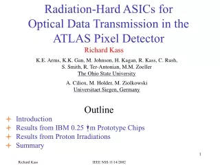
Radiation-Hard ASICs for Optical Data Transmission in the ATLAS Pixel Detector. K.E. Arms, K.K. Gan, M. Johnson, H. Kagan, R. Kass, C. Rush, S. Smith, R. Ter-Antonian, M.M. Zoeller The Ohio State University A. Ciliox, M. Holder, M. Ziolkowski Universitaet Siegen, Germany. Richard Kass.

Richard Kass
E N D
Presentation Transcript
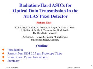
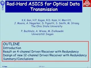
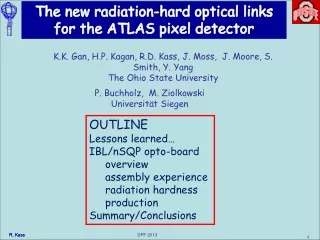
Radiation-Hard ASICs forOptical Data Transmission in theATLAS Pixel Detector K.E. Arms, K.K. Gan, M. Johnson, H. Kagan, R. Kass, C. Rush, S. Smith, R. Ter-Antonian, M.M. Zoeller The Ohio State University A. Ciliox, M. Holder, M. Ziolkowski Universitaet Siegen, Germany Richard Kass Outline l Introduction l Results from IBM 0.25 mm Prototype Chips l Results from Proton Irradiations l Summary IEEE NSS 11/14/2002
ATLAS Pixel Detector 2 disks/end 2 layers in barrel l Inner most charged particle tracking detector l Pixel size: 50 mm x 400 mm l ~ 100 million channels l Dosage after 10 years: middle barrel layer: 50 Mrad or 1015 1-MeV neq/cm2 optical link: 30 Mrad IEEE NSS 11/14/2002
ATLAS Pixel Opto-link VCSEL:Vertical Cavity Surface Emitting Laser diode VDC:VCSEL Driver Circuit PIN:PiNdiode DORIC:Digital Optical Receiver Integrated Circuit IEEE NSS 11/14/2002
VCSEL Driver Circuit Specs • Convert LVDS input signal into single-ended signal appropriate to drive the VCSEL diode • Output (bright) current: 0 to 20 mA, controlled by external voltage • Standing (dim) current: ~ 1 mA to improve switching speed • Rise & fall times: 1 ns nominal (80 MHz signals) • Duty cycle: (50 +/- 4)% • “On” voltage of VCSEL: up to 2.3 V at 20 mA for 2.5 V supply • Constant current consumption! IEEE NSS 11/14/2002
Digital Optical Receiver IC Specs lDecode Bi-Phase Mark encoded (BPM) clock and command signals from PIN diode lInput signal: 40-600 mA lExtract: 40 MHz clock lDuty cycle: (50 +/- 4)% lTotal timing error: <1 ns lBit Error Rate (BER): < 10-11 at end of life 40 MHz clock command BPM lTraining period: ~25 ms of 20 MHz clock (BPM with no data) Input transitions ] leadingedges Internal delays] trailingedges IEEE NSS 11/14/2002
VDC & DORIC Design History lOriginal design for ATLAS SemiConductor Tracker (SCT) AMS 0.8 mm BiPolar in radiation tolerant process (4 V) lDMILL: Summer 1999 - May 2001 3 submissions 0.8 mm CMOS rad-hard process (3.2 V) VDC & DORIC #3: meet specs Severe degradation of circuit performance in April 2001 proton irradiation lMigrate to IBM in Spring 2001 0.25 mm CMOS (2.5 V) 4 submissions to date Will present results from 4th IBM submission “I4” IEEE NSS 11/14/2002
VDC-I4: VCSEL Drive Currents vs Iset Turning over at high Iset is due to 10 W in series used in measurement Dependence of bright current vs Iset is as expected Need to increase bright (VDC-I3 reached 20 mA) and dim (1 mA) currents VDC-I5 is predicted to produce more current VDC Duty Cycle vs Iset for 40 MHz Clock operating range Clock duty cycle close to 50% Rise & fall times: 1.0-1.5 ns over operating range IEEE NSS 11/14/2002
Performance of DORIC I4 PIN Current Thresholds in DORIC-I4 Jitter of Recovered Clock in DORIC-I4 Jitter is low for low PIN current Jitter is large for high PIN current due to kludge used to get DORIC to work with common cathode PIN PIN current thresholds for no bit error are low: ~ 15 mA IEEE NSS 11/14/2002
Period/Duty Cycle of Recovered Clock in DORIC-I4 Clock duty cycle is close to 50% Clock period is close to 25 ns IEEE NSS 11/14/2002
VDC-I4 Irradiation Studies Irradiated opto-electronics with 24 GeV protons at CERN VDC Clock duty cycle increases by ~ 2% after 57 Mrad VDC bright and dim currents constant after 57 Mrad VCSEL Drive Current of Irradiated VDC-I4 No significant degradation from irradiation after 57 Mrad IEEE NSS 11/14/2002
Opto-Board Irradiation Study VECSEL’s, VDC’s, DORIC’s mounted on FR4 prototype opto-board Exposed to 24 GeV protons at CERN System used optical readout to compare sent and returned data Opto-pack clock PIN DORIC PIN array 4-channel DORIC-I4 data VDC VCSEL VCSEL VDC VCSEL array 4-channel VDC-I4 IEEE NSS 11/14/2002
Opto-Board Bit Error Threshold vs. Dosage VCSELs annealed with 20 mA during indicated periods Bit error thresholds remain constant up to 21 Mrad Opto-Board Optical Power vs. Dosage Optical power above the ATLAS pixel design specs IEEE NSS 11/14/2002
Summary lVDC-I4 & DORIC-I4 (IBM 0.25 mm) meet ATLAS pixel specs l opto-link passes ATLAS pixel radiation hardness specs ] continue to perform well after 20-58 Mrad! lNext VDC/DORIC submission: Dec. 2002 improve speed & amplitude of common cathode VDC implement common cathode preamp in DORIC IEEE NSS 11/14/2002
Extra Transparencies IEEE NSS 11/14/2002
DORIC Logic IEEE NSS 11/14/2002
VDC & DORIC Designs in 0.25mm lIBM #1-2: June - October 2001 VDC: decouple adjustment of bright & dim currents more constant current consumption DORIC: optimized differential preamp circuit a both circuits meet specs lIBM #3: November 2001 VDC: further improvements in current consumption DORIC: single-ended preamp keeps 10 V PIN bias off chip improved delay control circuit… a single-ended preamp matches prior performance lIBM #4: April 2002 VDC: compatible with common cathode VCSEL arrays, 4-channel chip DORIC: preamp optimized for common anode PIN arrays improved delay control circuit: centers clock at 50% duty cycle reset added for slow and controlled recovery…4-channel chip a improved performance over #3 IEEE NSS 11/14/2002