Download
1 / 64
640 likes | 754 Views
Beam Delivery System and Interaction Region of a Linear Collider. Nikolai Mokhov, Mauro Pivi, Andrei Seryi. The US Particle Accelerator School January 15-26, 2007 in Houston, Texas. Lecture RECENT DESIGN DEVELOPMENTS. Evolution of ILC BDS design in 2006. Vancouver baseline. Diagnostics BSY

E N D
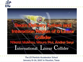
Beam Delivery System and Interaction Region of a Linear Collider Nikolai Mokhov, Mauro Pivi, Andrei Seryi The US Particle Accelerator School January 15-26, 2007 in Houston, Texas
Evolution of ILC BDS design in 2006 Vancouver baseline Diagnostics BSY tune-up dump 2mr IR b-collim. E-collim. 20mr IR Two collider halls separated longitudinally by 138m FF Valencia baseline 14mr IR 14mr IR One collider hall
14(20)mrad IR BNL, B.Parker, et al
FD14 design Interface region being optimized with forward detector region Sizes optimized for detector opening BNL Feedback kicker area Focus on 14mr design to push technologySize and interface of shared cryostat being optimized with detectorFeedback area being designed
2mrad IR Shared Large Aperture Magnets Disrupted beam & Sync radiations Q,S,QEXF1 SF1 QF1 SD0 QD0 60 m Beamstrahlung Incoming beam pocket coil quad Rutherford cable SC quad and sextupole
Losses in extraction line 100W/m hands-on limit 20mrad 20mr: losses < 100W/m at 500GeV CM and 1TeV CM2mr: losses are at 100W/m level for 500GeV CM and exceed this level at 1TeVRadiation conditions and shielding to be studied Losses are mostly due to SR. Beam loss is very small 2mrad 250GeV Nominal, 0nm offset 100W/m 45.8kW integr. loss Losses are due to SR and beam loss J. Carter, I. Agapov, G.A. Blair, L. Deacon (JAI/RHUL), A.I. Drozhdin, N.V. Mokhov (Fermilab), Y.M. Nosochkov, A.A. Seryi (SLAC)
Benchmarks for evaluation of ILC detectors Reaction which cares most about crossing angle is Detection is challenged by copious which require low angle tagging. Tagging is challenged by background from pairs and presence of exit hole Physics Benchmarks for the ILC Detectors, hep-ex/0603010, M. Battaglia, T. Barklow, M. E. Peskin, Y. Okada, S. Yamashita, P. Zerwas
Study of SUSY reach • SUSY reach is challenged for the large crossing angle when Dm (slepton-neutralino) is small • Studies presented at Bangalore (V.Drugakov) show that for 20mrad+DID (effectively ~40mrad for outgoing pairs), due to larger pairs background, one cannot detect SUSY dark matter if Dm=5GeV • The cases of 20 or 14mrad with anti-DID have same pairs background as 2mrad. Presence of exit hole affects detection efficiency slightly. The SUSY discovery reach may be very similar in these configurations • Several groups are studying the SUSY reach, results may be available after Vancouver
Backscattering of SR Photon flux within 2 cm BeamCal aperture: Flux is 3-6 times larger than from pairs. More studies & optimization needed SR from 250 GeV disrupted beam, GEANT FD produce SR and part will hit BYCHICMB surface Total Power = 2.5 kW <Eg>=11MeV (for 250GeV/beam) From BYCHICB Takashi Maruyama
Downstream diagnostics evaluation (1) Compton IP (cm) Study achievable precision of polarization and energy measurements, background & signal/noise, requirements for laser, etc. GEANT tracking in extraction lines Compton Detector Plane 20mrad 2mrad Ken Moffeit, Takashi Maruyama, Yuri Nosochkov, Andrei Seryi, Mike Woods (SLAC), William P. Oliver (Tufts University), Eric Torrence (Univ. of Oregon)
Downstream diagnostics evaluation (2) comparable with the goal for E precision measurements
Brainstorm to design magnets in 2mrad extraction Some magnet sizes on this drawing are tentative
Brainstorm for 2mrad magnets BHEX1 Recent suggestions Power @ 1TeV CM is 1MW/magnet. Temperature rise is very high. Use of HTS? Pulsed? Further feasibility study and design optimization are needed QEX5 Power @ 1TeV CM is 635-952 KW/magnet. Pulsed may be feasible? should have 6-60GS field! B1 > 2m beamstrahlung Vladimir Kashikhin , Brett Parker, John Tompkins, Cherrill Spencer, Masayuki Kumada, Koji Takano, Yoshihisa Iwashita, Eduard Bondarchuk, Ryuhei Sugahara QEX3
Magnets • Things to care: • needed aperture, L • strength, field quality, stability • losses of beam or SR in the area • E.g., extraction line => need aperture r~0.2m and have beam losses => need warm magnets which may consume many MW => may cause to look to new hybrid solutions, such as high T SC magnets
Magnet current (Amp*turn) per coil and total power Bend I(A)=B(Gs)*h(cm)*10/(4p) P(W)=2*I(A)*j(A/m2)*r(W*m)*l(m) Quad I(A)=1/2*B(Gs)*h(cm)*10/(4p) P(W)=4*I(A)*j(A/m2)*r(W*m)*l(m) I(A)=1/3*B(Gs)*h(cm)*10/(4p) Sextupole P(W)=6*I(A)*j(A/m2)*r(W*m)*l(m) For dipole h is half gap. For quad and sextupole h is aperture radius, and B is pole tip field. Typical bends may have B up to 18kGs, quads up to 10kGs. Length of turn l is approximately twice the magnet length. For copper r~2*10-8W*m. For water cooled magnets the conductor area chosen so that current density j is in the range 4 to 10 A/mm2
Drivers of the cost and Dcost Total Cost • Cost drivers • CF&S • Magnet system • Vacuum system • Installation • Dumps & Colls. • Drivers of splits between 20/2: • CF&S • Magnet system • Vacuum system • Dumps & collimators • Installation; Controls Additional costs for IR20 and IR2
from MDI panel statement • The physics mode most affected by crossing angle is the slepton pair production where the slepton-LSP Dm is small. The main background is 2-g processes and an efficient low-angle electron tag by BEAMCAL is needed to veto them. • Difference in expected background (is due to) different levels of veto efficiency. Signal to noise will be ~4 to 1 with 2mrad crossing angle. • For a large crossing angle (14 or 20mrad), anti-DID is needed to collimate the pair background along the outgoing beam. For 14mrad crossing with anti-DID, the … background is expected to be comparable to the 2mrad case while the signal efficiency reduces by about 30% to 40%. This is mainly due to the 2nd hole of BEAMCAL that is needed for the large crossing angle which will force additional cuts to remove the 2-photon and other backgrounds. • for 20mrad crossing with anti-DID was found to be essentially the same as the 2mrad case.
Valencia 14/14 baseline. Conceptual CFS layout muon wall tunnel widening polarimeter laser borehole 9m shaft for BDS access IP2 10m IP1 beam dump service hall alcoves 1km
CFS designs for two IRs Vancouver Valencia
Beam Delivery System tunnels 9m shaft for BDS access & service hall muon wall tunnel widening alcoves beam dump service hall beam dump and its shield
On-surface assembly : CMS approach • CMS assembly approach • Assembled on the surface in parallel with underground work • Allows pre-commissioning before lowering • Lowering using dedicated heavy lifting equipment • Potential for big time saving • Reduces size of required underground hall
BDS with single IR BSY Sacrificial collimators b-collim. E-collimator Diagnostics FF 14mr IR Tune-up dump Extraction
betatron collimation septa MPS coll skew correction / emittance diagnostic polarimeter fast kickers fast sweepers tuneup dump beta match final transformer polarimeter energy collimation IP primary dump energy spectrometer fast sweepers energy spectrometer final doublet
500GeV => 1TeV CM upgrade in BSY of 2006e “Type B” (×4) fast kickers septa polarimeter chicane QFSM1 moves ~0.5 m Magnets and kickers are added in energy upgrade M. Woodley et al
Single IR BDS optics (2006e) BSY FF Polarimeter E-spectrometer E-collimator b-collim. Diagnostics
Concept of single IR Final Doublet vacuum connection & feedback kicker common stationary cryostat Detector QD0 QF1 warm IP Original FD and redesigned for push-pull (BNL) Redesigned FD
IR magnets BNL prototype of sextupole-octupole magnet BNL prototype of self shielded quad cancellation of the external field with a shield coil has been successfully demonstrated at BNL
New optics for extraction FD : push pull compatible • Rearranged extraction quads are shown. Optics performance is very similar. • Both the incoming FD and extraction quads are optimized for 500GeV CM. • In 1TeV upgrade would replace (as was always planned) the entire FD with in- and outgoing magnets. In this upgrade, the location of break-point may slightly move out. (The considered hall width is sufficient to accommodate this). Nominal scheme Push-pull scheme B.Parker, Y.Nosochkov et al. http://ilcagenda.cern.ch/conferenceDisplay.py?confId=1187
Extraction Lines : shortened by 100m For undisrupted beam reliance on beam sweeping on beam dump window using kickers. high L parameters (500 GeV CM) Total loss before and at collimators for High L parameters is within acceptable levels. Losses for the nominal case are negligible.
Concept of single IR with two detectors detector B The concept is evolving and details being worked out may be accessible during run detector A accessible during run Platform for electronic and services (~10*8*8m). Shielded (~0.5m of concrete) from five sides. Moves with detector. Also provide vibration isolation.
Detector systems connections detector service platform or mounted on detector detector low V DC for electronics high V AC 4K LHe for solenoids low V PS high I PS electronic racks 4K cryo-system 2K cryo-system gas system 2K LHe for FD high P room T He supply & return sub-detectors solenoid antisolenoid FD high I DC for solenoids chilled water for electronics high I DC for FD gas for TPC fiber data I/O electronics I/O fixed connections long flexible connections move together
Push-pull cryo configuration Optimized for fast switch of detectors in push-pull and fast opening on beamline QD0 part QF1 part This scheme require lengthening L* to 4.5m and increase of the inner FD drift Opening of detectors on the beamline (for quick fixes) may need to be limited to a smaller opening than what could be done in off-beamline position door central part
Wall 25 rem/hr IR & rad. safety 18MW loss on Cu target 9r.l \at s=-8m. No Pacman, no detector. Concrete wall at 10m. Dose rate in mrem/hr. • For 36MW MCI, the concrete wall at 10m from beamline should be ~3.1m 10m
Self-shielding detector Detector itself is well shielded except for incoming beamlines A proper “pacman” can shield the incoming beamlines and remove the need for shielding wall 18MW on Cu target 9r.l at s=-8m Pacman 1.2m iron and 2.5m concrete 18MW lost at s=-8m. Packman has Fe: 1.2m, Concrete: 2.5m dose at pacman external wall dose at r=7m 0.65rem/hr (r=4.7m) 0.23rem/hr
Shielding the IR hall 250mSv/h Self-shielding of GLD Shielding the “4th“ with walls
Working progress on IR design… Mobile Shield Wall Illustration of ongoing work… Designs are tentative & evolving Structural Rib 3m Thickness Overlapping Rib Mobile Platform 20m x 30m Electronics/Cryo Shack 1m Shielded 25m Height 9m Base John Amann
Working progress on IR design… Pac Man Open Illustration of ongoing work… Designs are tentative & evolving Recessed Niche Pac Man Closed Beam Line Support Here John Amann
Working progress on IR design… CMS shield opened Looking into experience of existing machines… pacman opened SLD pacman closed pacman open door tunnel pacman closed
Air-pads at CMS Single air-pad capacity ~385tons (for the first end-cap disk which weighs 1400 tons). Each of air-pads equipped with hydraulic jack for fine adjustment in height, also allowing exchange of air pad if needed. Lift is ~8mm for 385t units. Cracks in the floor should be avoided, to prevent damage of the floor by compressed air (up to 50bars) – use steel plates (4cm thick). Inclination of ~1% of LHC hall floor is not a problem. Last 10cm of motion in CMS is performed on grease pads to avoid any vertical movements. [Alain Herve, et al.] Photo from the talk by Y.Sugimoto, http://ilcphys.kek.jp/meeting/lcdds/archives/2006-10-03/ 14kton ILC detector would require ~36 such air-pads
Displacement, modeling Starting from idealized case: -- elastic half-space (Matlab model) -- simplified ANSYS model (size of modeled slab limited by memory) Short range deformation (~0.1mm) is very similar in both models. Long range (1/r) deformation (~0.3mm) is not seen in ANSYS because too thin slab in the model More details (3d shape of the hall, steel plates on the floor, etc.) to be included. Long term settlement, inelastic motion, etc., are to be considered. Parameters: M=14000 ton; R=0.75m (radius of air-pad); E=3e9 kg/m^2, n=0.15 (as for concrete); Number of air-pads=36 Matlab model, half-space ANSYS model J.Amann, http://ilcagenda.cern.ch/conferenceDisplay.py?confId=1225
Schedule for the design goal time (a.u.) • The hardware can be designed to be compatible with a ~one day move, and this can be a design goal • Need to study cost and reliability versus the move duration • Need to study regulations in each regions • Recalibration (at Z) may or may not be needed, and may be independent on push-pull – to be studied
Crab crossing x factor 10 reduction in L! use transverse (crab) RF cavity to ‘tilt’ the bunch at IP x RF kick
Crab cavity requirements Crab Cavity IP ~0.12m/cell ~15m Use a particular horizontal dipole mode which gives a phase-dependant transverse momentum kick to the beam Actually, need one or two multi-cell cavity Slide from G. Burt & P. Goudket
View from top Electric Field in red Beam Magnetic field in green For a crab cavity the bunch centre is at the cell centre when E is maximum and B is zero TM110 Dipole mode cavity