
Comprehensive Overview of the 8085 Microprocessor Architecture and Functions
E N D
Presentation Transcript
8085 Microprocessor: Architecture & Support Components
Contents • Pin diagram of 8085 • 8085 Operations • Architecture of 8085 • 8085 Communication with Memory
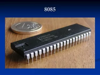
Pinout Diagram of 8085 • A 40-pin IC • Six groups of signals • Address Bus • Data Bus • Control and Status pins • Power Supply & frequency signals • Externally initiated Signals • Serial I/O ports
Logic Pinout of 8085 Power Supply & frequency Data Bus Address Bus Serial I/O ports Externally initiated signals Control & Status Control & Status
8085 Operations • Microprocessor Initiated Operations • Internal Operations • Peripheral/Externally Initiated Operations
Microprocessor Initiated Operations • Memory Read • Memory Write • I/O Read • I/O Write
Internal Operations • Store 8-bit data • Perform Arithmetic and Logic Operations • Test for conditions • Sequence the execution of instructions • Store/Retrieve data from stack during execution
Peripheral/Externally Initiated Operations • Reset • Interrupt • Ready • Hold
Architecture of 8085 • Power Supply – a +5V DC power supply • Maximum clock frequency of 3MHz • 8-bit general purpose microprocessor • 16-bit Address Bus • Capable of addressing 64K of memory
ALU Timing and Control Unit General Purpose Registers Program Status word Program Counter Stack Pointer Instruction Register and Decoder Interrupt Control Serial I/O Control Address Bus Data Bus Architecture 0f 8085 Cont…
Architecture 0f 8085 Cont… • Arithmetic Logic Unit (ALU) • 8085 has 8-bit ALU • Performs arithmetic & Logic operations on data • Timing & Control Unit • Generates timing and control signals • General Purpose Registers • 8-bit registers (B,C,D,E,H,L) • 16-bit register pairs (BC, DE, HL,PSW)
Architecture 0f 8085 Cont… • Program Status Word (PSW) • Accumulator and Flag Register can be combined as a register pair called PSW • Instruction Register and Decoder • Instruction fetched from memory is stored in Instruction register (8-bit register) • Decoder decodes the instruction and directs the Timing & Control Unit accordingly
Architecture 0f 8085 Cont… • Interrupt Control • 8085 has 5 interrupt signals • INTR – general purpose interrupt • RST 5.5 Restart Interrupts • RST 6.5 • RST 7.5 • TRAP – non-maskable interrupt • The interrupts listed above are in increasing order of priority
Architecture 0f 8085 Cont… • Serial I/O Control • 8085 has two signals for serial communication • SID – Serial Input Data • SOD – Serial Output Data
Architecture 0f 8085 Cont… • Address Bus • Used to address memory & I/O devices • 8085 has a 16-bit address bus Higher-order Address Lower-order Address Data Bus • Data Bus • Used to transfer instructions and data • 8085 has a 8-bit data bus
8085 Communication with Memory • Involves the following three steps • Identify the memory location (with address) • Generate Timing & Control signals • Data transfer takes place
1 3 2
Demultiplexing Address/Data Bus • 8085 identifies a memory location with its 16 address lines, (AD0 to AD7) & (A8 to A15) • 8085 performs data transfer using its data lines, AD0 to AD7 • Lower order address bus & Data bus are multiplexed on same lines i.e. AD0 to AD7. • Demultiplexing refers to separating Address & Data signals for read/write operations
Need for Demultiplexing… RD A8-A15 8085 Memory 20H AD0-AD7 05H 4FH 2005H
8085 Interfacing with Memory chips Address Address Memory Interface Memory Chip Data Data 8085 Control Control
8085 Interfacing with Memory chips Data Memory Chip 74LS373 8085 AD0-AD7 A0 – A7 ALE A8-A15 A8-A15 Control Memory Interface
8085 Interfacing with Memory chips Data Program Memory 74LS373 8085 AD0-AD7 A0 – A7 ALE A8-A15 A8-A15 CS IO/M RD RD Memory Interface
Memory Mapping • 8085 has 16-bit Address Bus • The complete address space is thus given by the range of addresses 0000H – FFFFH • The range of addresses allocated to a memory device is known as its memory map
Memory map: 64K memory device • Address lines required: 16 (A0 – A15) • Memory map: 0000H - FFFFH • So the memory map is A11 to A0 0…. 0 0 = 0000H to A11 to A0 1…. 111 = FFFFH
Interfacing I/O devices with 8085 Peripheral-mapped I/O & Memory-mapped I/O
Interfacing I/O devices with 8085 I/O Interface I/O Devices 8085 System Bus Memory Interface Memory Devices
Techniques for I/O Interfacing • Memory-mapped I/O • Peripheral-mapped I/O
Memory-mapped I/O • 8085 uses its 16-bit address bus to identify a memory location • Memory address space: 0000H to FFFFH • 8085 needs to identify I/O devices also • I/O devices can be interfaced using addresses from memory space • 8085 treats such an I/O device as a memory location • This is called Memory-mapped I/O
Peripheral-mapped I/O • 8085 has a separate 8-bit addressing scheme for I/O devices • I/O address space: 00H to FFH • This is called Peripheral-mapped I/O or I/O-mapped I/O
8085 Communication with I/O devices • Involves the following three steps • Identify the I/O device (with address) • Generate Timing & Control signals • Data transfer takes place • 8085 communicates with a I/O device only if there is a Program Instruction to do so
1.Identify the I/O device (with address) • Memory-mapped I/O (16-bit address) • Peripheral-mapped I/O (8-bit address)
2.Generate Timing & Control Signals • Memory-mapped I/O • Reading Input: IO/M = 0, RD = 0 • Write to Output: IO/M = 0, WR = 0 • Peripheral-mapped I/O • Reading Input: IO/M = 1, RD = 0 • Write to Output: IO/M = 1, WR = 0 3. Data transfer takes place
Peripheral I/O Instructions • IN Instruction • Inputs data from input device into the accumulator • It is a 2-byte instruction • Format: IN8-bit port address • Example: IN01H
OUT Instruction • Outputs the contents of accumulator to an output device • It is a 2-byte instruction • Format: OUT8-bit port address • Example: OUT02H
----------Example Program---------- • WAP to read a number from input port (port address 01H) and display it on ASCII display connected to output port (port address 02H) IN01H ;reads data value 03H (example)into ;accumulator, A = 03H MVI B, 30H;loads register B with 30H ADD B ;A = 33H, ASCII code for 3 OUT02H ;display 3 on ASCII display
Memory-mapped I/O Instructions • I/O devices are identified by 16-bit addresses • 8085 communicates with an I/O device as if it were one of the memory locations • Memory related instructions are used • For e.g. LDA, STA • LDA8000H • Loads A with data read from input device with 16-bit address 8000H • STA8001H • Stores (Outputs) contents of A to output device with 16-bit address 8001H
----------Example Program---------- • WAP to read a number from input port (port address 8000H) and display it on ASCII display connected to output port (port address 8001H) LDA8000H;reads data value 03H (example)into ;accumulator, A = 03H MVI B, 30H;loads register B with 30H ADD B ;A = 33H, ASCII code for 3 STA8001H;display 3 on ASCII display
Show the Pinout of 8085 in several grpups. • Mention the operations of 8085 in group • Discuss the data bus and address bus and the multiplexing. • Short questions