Download
1 / 5
60 likes | 199 Views
Ultrasonic testing (UT) is a non-destructive technique that uses ultrasonic waves to detect flaws and characterize materials. This guide covers UT methods, including thickness measurement and Pulse Velocity testing of concrete, with detailed explanations and illustrations.

E N D
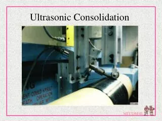
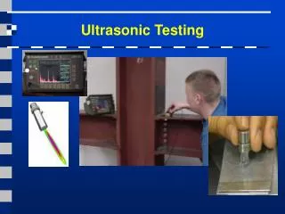
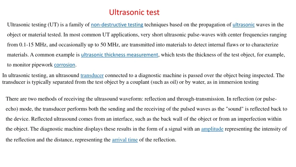
Ultrasonic test Ultrasonic testing(UT) is a family ofnon-destructive testingtechniques based on the propagation ofultrasonicwaves in the object or material tested. In most common UT applications, very short ultrasonic pulse-waves with center frequencies ranging from 0.1-15 MHz, and occasionally up to 50 MHz, are transmitted into materials to detect internal flaws or to characterize materials. A common example isultrasonic thickness measurement, which tests the thickness of the test object, for example, to monitor pipeworkcorrosion. In ultrasonic testing, an ultrasound transducer connected to a diagnostic machine is passed over the object being inspected. The transducer is typically separated from the test object by a couplant (such as oil) or by water, as in immersion testing There are two methods of receiving the ultrasound waveform: reflection and through-transmission. In reflection (or pulse-echo) mode, the transducer performs both the sending and the receiving of the pulsed waves as the "sound" is reflected back to the device. Reflected ultrasound comes from an interface, such as the back wall of the object or from an imperfection within the object. The diagnostic machine displays these results in the form of a signal with an amplitude representing the intensity of the reflection and the distance, representing the arrival time of the reflection.
In attenuation (or through-transmission) mode, a transmitter sends ultrasound through one surface, and a separate receiver detects the amount that has reached it on another surface after traveling through the medium. Imperfections or other conditions in the space between the transmitter and receiver reduce the amount of sound transmitted, thus revealing their presence. Using the couplant increases the efficiency of the process by reducing the losses in the ultrasonic wave energy due to separation between the surfaces. Figure -3- through-transmission mode
Also, Ultrasonic Pulse Velocity (UPV) testing of concrete is based on the pulse velocity method to provide information on the uniformity of concrete, cavities, cracks and defects. The pulse velocity in a material depends on its density and its elastic properties which in turn are related to the quality and the compressive strength of the concrete. It is therefore possible to obtain information about the properties of components by sonic investigations. Table -1- represents the concrete quality regards the pulse velocity Figure -4- UPV testing device