Download
1 / 18
180 likes | 318 Views
Development of a Portable Work Zone Traffic Safety Information System using DSRC Based V2I and V2V Communication. M Imran Hayee, Ph. D. ECE Department, University of Minnesota Duluth. Outline. What has been accomplished ? Phase I Phase II What is currently being accomplished?

E N D
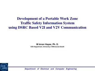
Development of a Portable Work Zone Traffic Safety Information System using DSRC Based V2I and V2V Communication M Imran Hayee, Ph. D. ECE Department, University of Minnesota Duluth
Outline • What has been accomplished? • Phase I • Phase II • What is currently being accomplished? • Phase III • What could be possible next phase?
What Has Been Done? – Phase 1 Year: 2008 - 2009 BT enabled Cell Phone CID DSRC RSU or OBU DSRC-OBU MNDOT Infrastructure • This system was developed and demonstrated in the field • Currently the Bluetooth enabled cell phone gets text messages
What Has Been Done? – Phase 2 Portable DSRC Based V2I Information System Year: 2009 - 2010 Start of Congestion (varying) Vehicle passing Through congested area End of Congestion Distance to SoC Vehicle approaching Congested area DSRC-RSU DSRC-OBU DSRC-OBU Work Zone Two way DSRC communication to acquire safety and traffic data SoC location and TT Broadcast from RSU It was developed and successfully demonstrated in the field. Can acquire in real time, important travel information e.g., TT and SoC location Can communicate to the driver, both TT and distance to the SoC location Uses BT enabled cell phone text messaging as user interface for the driver
System Setup End of Congestion: Known End of RSU Monitoring Range Start of RSU Monitoring Range Desired Location Start of Congestion: Unknown Work Zone Lane RSU Coverage range of RSU • RSU is placed such that the RSU monitoring range aligns with the end of the congestion. • At periodic intervals, a single OBU participation is requested by the RSU to monitor a vehicle’s speed and position through a congestion area. • RSU sends traffic alert message to OBUs indicating travel time through monitoring area.
DSRC Communication Protocol RSU OBU RSU OBU INVITE BROADCAST ACCEPT CHOSEN NOTIFY • RSU initiates the communication by sending an INVITE message requesting OBU participation. • Each OBU receiving the INVITE message screens itself using the information in INVITE message and if passes the screening, it will respond with the ACCEPT message. • The RSU will screen the incoming ACCEPT messages to ensure that the OBU is on the monitored road, and sends CHOSEN message to the originating OBU of the first ACCEPT message to pass. • OBU periodically communicates NOTIFY messages until EoC point approaching is detected, then RSU is alerted before OBU ceases to send further NOTIFY messages.
Field Testing (b) (a) X • The location accuracy of the GPS is the most important factor when determining the possible error in measurements. • The location accuracy error in turn causes errors in distance and direction measurements.
GPS Distance Accuracy Urban Area – accuracy is +/- 3 m Rural Area – accuracy is +/- 2 m
GPS Direction Accuracy A B A B Direction Error decreases if distance is increased
Field Demonstration Start of Congestion: Unknown End of Congestion: Known End of RSU Monitoring Range Start of RSU Monitoring Range RSU N • The field demonstration site was chosen at Rice Lake Rd, Duluth MN with the focus on providing a clear line of sight between RSU and the OBU. • The RSU is placed near the congestion end due to reduced range on one side due to signal blocking by back of the vehicle.
Traffic Safety Parameters • The traffic parameters - Start of Congestion location and the Travel Time are calculated by RSU • The update frequency is determined based upon the TT. If TT is larger, multiple vehicles are chosen at the same time to be monitored.
Field Demonstration Results • Congestion scenarios of varying start of congestion location and congestion depth were tested for different vehicle speeds.
What is Being Done? – Phase 3 The Range of the current system is limited to 1 km because of the DSRC antenna range. However the calculated traffic parameters of the system are more useful to the driver if its received earlier. Also congestion or a work zone area may exceed 1 km requiring more range to be covered. In the current phase 3 (2010-2011), the objective is to utilize the V2V DSRC communication to the developed Portable Work-Zone Safety Message Relay System to 1. Increasing the Message Broadcast Range 2. Increasing the Work-zone Coverage Length
Portable DSRC RSU Increasing the Message Broadcast Range 1 km 1 km 1 km V2I V2I V2V V2V We intend to increase the message broadcast range using V2V-assisted DSRC communication. To increase the message broadcast range, we propose to use the selected vehicles on the road approaching to work zone to help relay the traffic safety messages backwards to the vehicles following them, to achieve much longer message broadcast range without having an extensive DSRC roadside infrastructure.
Portable DSRC RSU Increasing the Work-zone Coverage Length 1 km 1 km 1 km V2I V2I V2V V2V V2V Similarly, we propose to use V2V-assisted communication to cover much longer work zones beyond the access range of one portable roadside DSRC unit. This will be accomplished with the help of selected vehicles present on the work zone well out of reach of the portable roadside DSCR unit to help facilitate V2V-assisted V2I traffic data exchange.
Progress of the Current Phase • Increasing the Message Broadcast Range • 1. V2V communication. • 2. Develop method for distance measurement adjustment vs. displacement. • 3.Develop and test the V2V communication protocol for extended range. • 4. Demonstrate the algorithm for distance adjustment in V2V environment • 2. Increasing the Work-zone Coverage Length • 1. Develop protocols for handling messages from other OBU’s in the OBU program. • 2. Develop protocols for extending and contracting the monitored area. • 3. Demonstrate the system in field. Note: The green tasks have been done and the blue tasks are being worked on. The project is expected to finish in time (during June/July 2010 time frame)
Curve Fitting Start of Congestion Curved Road Measured distance Straight Road The road curvature is statistically modeled by a polynomial fit, parameters of which can be communicated to the OBU so that it can adjust the measured displacement.
Portable DSRC RSU Portable DSRC RSU What Next? 1 km Current: V2V assisted V2I 1 km 1 km V2I V2I V2V V2V V2V 1 km Pure V2V ? 1 km 1 km V2I V2I V2V V2V V2V