Download
1 / 27
280 likes | 470 Views
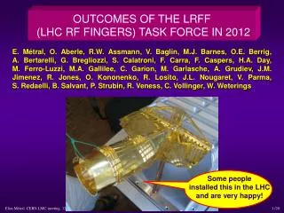
Electromagnetic Simulations of VMTSA Equipped with the RF Fingers and Ferrites. O. Kononenko CERN, BE/RF JINR Thanks to Benoit Salvant, Alexej Grudiev, Elias Métral LRFF Meeting, CERN, October 30, 2012. Outline.

E N D
Electromagnetic Simulations of VMTSA Equipped with the RF Fingers and Ferrites O. Kononenko CERN, BE/RF JINR Thanks to Benoit Salvant, Alexej Grudiev, Elias Métral LRFF Meeting, CERN, October 30, 2012
Outline • Realistic finger deformations for VMTSA equipped with the longer fingers. Time domain, eigen frequency and wire simulations • Simulations of the deformed shorter fingers and effect of Philips 8C11 ferrites
Simulated VMTSA models Old longer fingers New shorter fingers Conforming fingers Conforming and bad contact fingers Wire, conforming fingers Bad contact 1st type Wire, no fingers Bad contact 2st type Wire, 20-50mm gaps Deformation+Ferrites In progress Completed
VMTSA with Wire and Comforming Fingers • Model: • 180 deg of the structure • copper outer walls Perfect H Port 2 Copper Wire Port 1 • Simulation profile: • - second order basis functions • curvilinear elements enabled • discrete sweep from 20MHz to 2GHz, 20MHz step • 0.01 s-parameters accuracy => ~220K tet10 mesh - no matching
VMTSA with Wire and Deformed Fingers: 20-40mm gaps • Model: • 180 deg of the structure • copper outer walls Perfect H Port 2 Copper Wire Port 1 Gap: 20-40mm • Simulation profile: • - second order basis functions • curvilinear elements enabled • discrete sweep from 20MHz to 2GHz, 20MHz step • 0.01 s-parameters accuracy => ~260K tet10 mesh Gap - no matching
VMTSA with Wire andMore Realistic Deformation • Model: • 180 deg of the structure • copper outer walls Perfect H Port 2 Stainless Steel Wire Port 1 Gap: 40-50mm • Simulation profile: • - second order basis functions • curvilinear elements enabled • discrete sweep from 10MHz to 2GHz, 10MHz step • 0.01 s-parameters accuracy => ~300K tet10 mesh Gap - no matching load
Transmition for Different Gap Sizes Different level of transmission probably because there is no matching load in the HFSS simulation
CST TD Simulations of VMTSA • Model: • full structure • copper walls • conforming fingers and 40-50 mm gap • Simulation profile: • - 10 lines per wavelength • - refine at PEC by factor 6 • - 70mm bunch sigma • 400K hex mesh
HFSS Eigen Mode Analysis: 40mm Longitudinal Shunt Impedance Voltage along the beam path Energy stored in the volume
Surface Loss Density for the First Eigen Mode @ 279 MHz Log scale, 40 mm gap, eigen mode @ 279MHz with 10KΩ longitudinal shunt impedance
Shorter RF FingersHFSS Simulation Setup: Eigensolver • Model: • 180 deg of the structure • copper outer walls • 10mm gap Perfect H Copper 10 mm gap • Simulation profile: • - second order basis functions • curvilinear elements enabled • 1% frequency accuracy leads to ~300K tet10 mesh
Shorter RF Fingers, CmplxMag(E) Eigenmodes of the Bellows
VMTSA equipped with Ferrites 4 pieces of Philips 8C11 (60x30x5 mm) were installed in one VMTSA module equipped with the shorter fingers
Philips 8C11 Ferrite: Permeability http://www.ferroxcube.com/appl/info/HB2009.pdf
Philips 8C11 Ferrite: Resistivity and Permittivity http://www.ferroxcube.com/appl/info/HB2009.pdf
HFSS Setup • Model: • 180 deg of the structure • copper outer walls • 10mm gap • 4 ferrite pieces Ferrite 8C11 Perfect H Copper 10 mm gap • Simulation profile: • - second order basis functions • curvilinear elements enabled • 1% frequency accuracy
New Fingers Ferrites 10mm Many modes excited in the vicinity of ferrites and in the area outside the conforming fingers. Some modes excited near to the gap and not affected by ferrites at all
Surface Loss Density for the First Eigen Mode @ 341 MHz Linear scale, 10 mm gap, eigen mode @ 341MHz with 2700 W power losses
Conclusions • Different shapes of the finger deformations have been studied for longer and shorter fingers. Unconformities could result in ~kW power losses => enough to melt fingers. • Ferrites in the proposed position and amount don’t help. Additional dedicated study is necessary to see if we can damp modes with ferrites.