Download
1 / 41
410 likes | 564 Views
KAVM Switch. Richard Cantzler & Grant Farrand. ECE 345 – Senior Design December 4 th , 2003. Introduction. The KAVM Switch is a device that allows you to easily control many PS/2 computers with a single PS/2 keyboard, video and mouse console.

E N D
KAVM Switch Richard Cantzler & Grant Farrand ECE 345 – Senior Design December 4th, 2003
Introduction The KAVM Switch is a device that allows you to easily control many PS/2 computers with a single PS/2 keyboard, video and mouse console. Although this device is already in the market, we improved upon existing products by adding: • Output VGA (So you can still keep your monitor attached!) • Multiple video formats (So you can even watch on your TV!) • Design for easy integration with wireless transceivers!
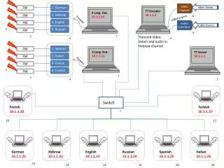
Description Base Station Sends: Keyboard data Mouse data Receives: Audio data Video data Remote Station Sends: Audio data Video data Receives: Keyboard data Mouse data Router Sends data between the Base Station and Remote Stations in the same manner as a wireless transceiver.
The Hardware Base Station Sends: Keyboard data Mouse data Receives: Audio data Video data Remote Station Sends: Audio data Video data Receives: Keyboard data Mouse data Router Sends data between the Base Station and Remote Stations in the same manner as a wireless transceiver.
Base Station Overview • The Base Station is comprised of: • Power Supply • Provides +5, +3.3, -5, and GND at up to 1 A. • Control Channel Processor Unit (CCPU) • Handles processing of the menu and the network traffic • Button & Switch Board • Allows user to interface with CCPU • Audio Receiver • Status LED Board
Remote Station Overview • The Remote Station is comprised of: • Power Supply • Provides +5, +3.3, -5, and GND at up to 1 A. • Control Channel Processor Unit (CCPU) • Handles processing of the menu and the network traffic • Button & Switch Board • Allows user to interface with CCPU and to set RS ID • Audio Transmitter • Video Converter Board • Status LED Board
Power Supply The Power Supply is based on a design using linear regulators. It preferably takes a 6.25V input (to maximize efficiency) and converts it to +5, +3.3, -5 and GND, although the input is rated from 6.25V up to 36V. There is an adjustable control voltage that takes part of the output voltage and resistively divides that back to ground, using this current to control the output voltage.
Power Supply Under 9V input, 43mA draw Tall: 2mV/div Wide: 20ns/div Under 9V input, 43mA draw Beat period is 140ns (7.1429 MHz), Max spike is 25mV. Tall: 5mV/div Wide: 100ns/div
Control Channel Processing Unit • The CCPU is an 18F452 PIC that processes the menu and network traffic. • Interfaces with Button & Switch Board to get button inputs and to read RS ID’s. • Interfaces with the Router to allow network connectivity. • The code for the CCPU was not part of this senior design project. • It was created for ECE 246.
Keyboard Clock & Data Tall: 5V/div Wide: 200us/div
Button & Switch Board • The Button & Switch Board provides our user inputs to the CCPU. It is comprised of: • Push Buttons (with debouncer circuits) • DIP Switches (for setting RS ID’s) • The debouncer circuits are TIMER555’s connected in an R-C circuit of 10pF and 10KΩ (debounced period of 100 us). • The DIP Switches are current sourced through pull up resistors to the parallel load of a shift register. The CCPU sends signals to load the data and read it in serially.
Button & Switch Board Tall: 2V/div Wide: 200us/div Tall: 2V/div Wide: 50us/div Tall: 2V/div Wide: 20ms/div
Audio Transmitter • The Audio Transmitter is located on each Remote Station and transmits audio to the Base Station’s Audio Receiver. • It makes use of a Linx HP-II series transmitter at 900 MHz • The audio input signal is assumed to have a max of ## volts (standard sound card output). • The signal is amplified (?) to have a max of 3-Vpp. • It is biased at 1.5 volts so it swings from 3 volts down to 0. • The signal is then sent to the HP-II’s analog input pin.
Audio Receiver • The Audio Receiver is located on each Base Station and receives audio from the Remote Station’s Audio Transmitter. • It makes use of a Linx HP-II series receiver at 900 MHz • The signal is taken from the HP-II’s analog output pin. • The output of the amplifier is AC coupled (## V-pp).
Video Conversion Board The Video Conversion Board allows the VGA output from the computer to be viewed in NTSC or PAL form on a television. The conversion is performed by the AD725AR which provides both composite video and S-video outputs. The board also buffers the VGA signal to provide a VGA out signal so a monitor can still be attached during operation. The VGA output must be 1024x768, 60 Hz vertical scan, and 15.575 KHz horizontal scan.
Status LED Board • The Status LED Board provides viewing of the device’s state. • The following signals are connected: • Power • Inbound Data • Outbound Data • Link (connected to server) • Enable (data channel is active) • The LED’s are not sourced, and were calibrated to draw approximately 10mA of current each.
The Software Base Station Initiates connections to the Remote Stations acting as masters. Remote Station Connect individually to the Base Station acting as slaves. • Main (BSCCPU.c & RSCCPU.c) • Menu (Menu.c) • Network (TXRX.c) • Miscellaneous (Misc.c) • Def’s (Global.c & Compiler.h) • LCD (GFlcd.c)
Code Base • Main (BSCCPU.c) • Sets up Interrupts (Counters and an ISR that checks lines for incoming data). • Initializes the other functions and loops “DisplayMenu” & “ProcessCCData”. • Menu (Menu.c) • DisplayMenu: Checks for input button signals, and calls respective functions. • MoveLeft & MoveRight: Update menu position respectively. • Select: Updates menu position and determines if something is “Active”. • Redisplay: Displays the text based on the menu position and “Active” signal. • Network (TXRX.c) • SendCCData: Sends data out from the send buffer. • ProcessCCData: Determines network state based on received data and performs necessary functions. Lights LED’s accordingly.
Code Base • Miscellaneous (Misc.c) • ReadID: Loads the ID from the switches into the register and reads it in serially. • ReadPKT: Loads data from the switches into the register and returns it. • DisplayError: Displays an error messages based on the error state. • Def’s (Global.c & Compiler.h) • Defines Pins, Network Packets, Menu States, and Error States. • LCD (GFlcd.c) • Uses Port B to interface with the LCD.
Main DisplayMenu ProcessCCData MoveLeft MoveRight Select Redisplay SendCCData ReadID LCD DisplayError ReadPKT Code Flowchart BS BS BS
Code Differences Base Station Network Acts as Master. Sends packets when prompted by user and when negotiating with Remote Stations. Sends Connect, Enable, and Disable Signals. Menu Has respective text and added option to Enable, Disable, and Change Channels. Def’s Definitions to accomplish the above Remote Station Network Acts as Slave. Sends packets to reply to the Base Station. Strictly sends replies to the Base Station. Only acts when a packet is followed by the Remote Client’s own ID. Menu Has respective text. . . Def’s Definitions to accomplish the above
Thanks! • Jim Wehmer • Josh Potts • Han Seok Kim & Ryan Mokos • Professors Swenson and Uribe • Various Distributors: • Digi-key • Analog Devices • Littlefuse • Parts Shop!
Clip Art Keyboard Audio Video Mouse