Understanding Capacitors in Electric Circuits: Reactance and Impedance
Learn about capacitance, reactance, impedance, and how capacitors behave in electric circuits under different conditions. Explore examples and calculations regarding capacitive reactance and current flow.

Understanding Capacitors in Electric Circuits: Reactance and Impedance
E N D
Presentation Transcript
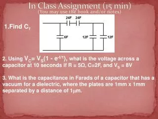
Find CT In Class Assignment (15 min) • 2. Using VC= VS(1 - e-t/), what is the voltage across a capacitor at 10 seconds if R = 5Ω, C=2F, and VS = 8V • 3. What is the capacitance in Farads of a capacitor that has a vacuum for a dielectric, where the plates are 1mm x 1mm separated by a distance of 1m. (You may use the book and/or notes)
Chapter 21 Review • What is ? • How many Tau does it take to get exactly charge a capacitor to 75% of being fully charged? • How long does it take to charge a capacitor to fully charged if there is no resistor in the circuit? • A capacitor acts like a ___________ under DC conditions and an ____________ under high frequencies. • Today we will learn how capacitors and inductors act under normal frequencies open short
Short, Medium, and Long ’s • A long time constant is defined as one in which the RC time constant (τ) is at least five times longer, in time, than the pulse width of the applied waveform. As a result, the capacitor of a series RC circuit accumulates very little charge, and VCremains small. Draw VC
Short, Medium, and Long ’s • A medium time constant is defined as one in which the RC time constant (τ), in time, is equal to the pulse width of the applied waveform. As a result, the voltage across the capacitor of a series RC circuit falls between that of a long and short time constant circuit. Draw VC An RC circuit can be used to convert a Square wave signal into a Triangle signal. Also known as an Integrator circuit.
Short, Medium, and Long ’s • A short time constant is defined as one in which the time constant is no more than one-fifth the pulse width, in time, of the applied voltage. Here, the capacitor quickly charges to the applied voltage and remains there until the input drops to zero. Then the capacitor quickly discharges to zero. Draw VC
Chapter 22 Capacitive and Inductive Reactance
AC signals • Keeping in mind: • Inductors act like shorts under DC and opens at instant change. • Capacitors act like opens under DC and shorts at instant change. • An AC signal is voltage level that is constantly changing. • Both inductors and capacitors resist this mid level voltage change. (Not 0Hz but not high freq either). • Since Sine waves are continuous, this resistance is constant. • In this sense, you can say capacitors are like constant resistors under steady AC waveforms.
Reactance – X (symbol for reactance) • The resistance or opposition that inductors and capacitors have towards an AC signal is not called resistance, it is called REACTANCE. • Reactance for a capacitor is labeled XC. • Reactance for an inductor is labeled XL. • If both resistance and reactance exist in a circuit, then this total opposition is called IMPEDANCE: • IMPEDANCE - THE TOTAL OPPOSITION TO CURRENT FLOW. • Impedance is labeled Z
RVOTD • http://www.wired.com/geekdad/2011/10/dont-blink-lego-nxts-and-a-smartphone-just-solved-your-rubiks-cube/
Capacitive Reactance XC • Because the plates of a capacitor are changing polarity at the same rate as the AC voltage, the capacitor seems to pass AC. • Suppose you put capacitor in series with your scope probes when you were measuring voltage signal that contained both AC and DC parts. What would your oscope show?
Capacitive Reactance XC • Capacitors have LESS reactance under 2 conditions: • (What do you think they are?) • 1. Increase in frequency • 2. Increase in Capacitance XC =
Finding Capacitive Reactance XC = • Ex: Determine the capacitive reactance XC of a 10uF capacitor when the frequency is 1kHz. • XC = • Ex: Determine the capacitive reactance XC of a .001uF capacitor when the frequency is 4kHz. • XC = = 15.9Ω = 39.8kΩ
Finding frequency and Capacitance XC = • Ex: Determine the frequency of a circuit if the resulting capacitive reactance XC is 300Ω of a 500nF capacitor. • f = • Ex: Determine the capacitor size if its capacitive reactance is 1000Ω at 50kHz. • C= = 1061 Hz = 3nF
Using Reactance to find Current • What is the current flowing in the circuit below? • However, this is not the whole story. • Capacitors don’t act purely like a resistor. Why? • There is a lag, as we will see in a few slides. XC = =132kΩ I =
Using Reactance to find Current XC1= =132kΩ • What is the current flowing in the circuit below? • Yes you could have combined the capacitors first. How would you do this? XC2= =265kΩ XT= 88kΩ Once you’ve converted Capacitors into resistances, treat them like resistors when doing the math. I =
Using Reactance to find Current • You can also combine all capacitors first. • What would be the total capacitance in this circuit? XC= =88kΩ I =
Capacitive Reactance Review • Why is XC measure in ohms? • What is the proportionality between f and XC? • What is the proportionality between f and XC?
Inductive Reactance XL • Capacitors have MORE reactance under 2 conditions: • (What do you think they are?) • 1. Increase in frequency • 2. Increase in Capacitance XL =
Finding Inductive Reactance XL = • Ex: Determine the inductive reactance XL of a 10mH inductor when the frequency is 1kHz. • XL= • Ex: Determine the inductive reactance XLof a 700uH inductor when the frequency is 35kHz. = 62.8Ω H = 154Ω XL=
Finding Capacitive Reactance XL = • Ex: Determine the frequency of a circuit if the resulting inductive reactance XL is 450Ω of a 50mH capacitor. • f = • Ex: Determine the inductor size if its inductive reactance is 1000Ω at 50kHz. • L = = 1432 Hz = 3.2mH
Using Reactance to find Current • What is the current flowing in the circuit below? • However, this is not the whole story. • Inductors don’t act purely resistive either. Why? • There is a lag, as we will see in a few slides. XL= Ω I = Can you graph this current
The Graph of an AC Current looks AC • The answer for current in the previous problem was 332mA. • This current would look sinusoidal if you graphed it. (Similar to voltage) It is not a flat signal. • Would this current be graphed as peak-to-peak? Peak? RMS? Average?
RVOTD • http://www.wimp.com/meltsrock/
Reactance is not purely resistance otherwise it would be called resistance • The difference between reactance and resistance is with reactance there is a delay of some sort. • Its called reactance because inductors and capacitors react to voltage changes, and it takes time to react, while resistors resist instantly as voltage changes.
Does capacitor current lead or lag capacitor voltage? ICE Current in a capacitor leads voltage in a capacitor
Does inductor voltage lead or lag inductor current? ELI Voltage in an inductor leads current in an inductor
A pneumonic for remembering the leading and lagging characteristics for inductors and capacitors is: ELI the ICEman
More Practice (with white boards?) • http://www.sweethaven.com/sweethaven/modelec/dcac/basicequs/default.asp