Download
1 / 52
520 likes | 569 Views
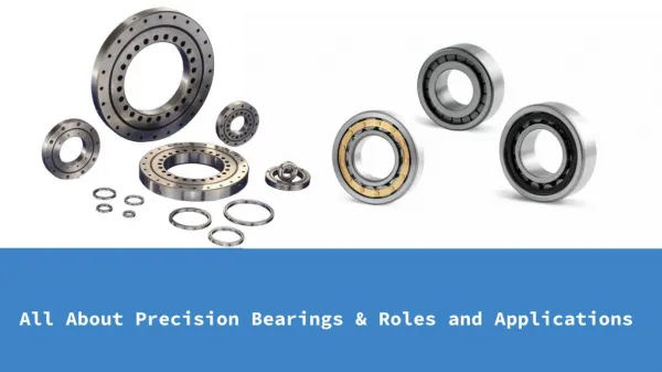
UNITEC, leading company in the design and manufacturing of special precision cylindrical roller bearings for machine tools and general industry, delivers high quality service and support to customers world-wide. To Know More Visit: http://www.carterbearings.co.uk/wp-content/themes/default/downloads/unitec/unitec.pdf

E N D
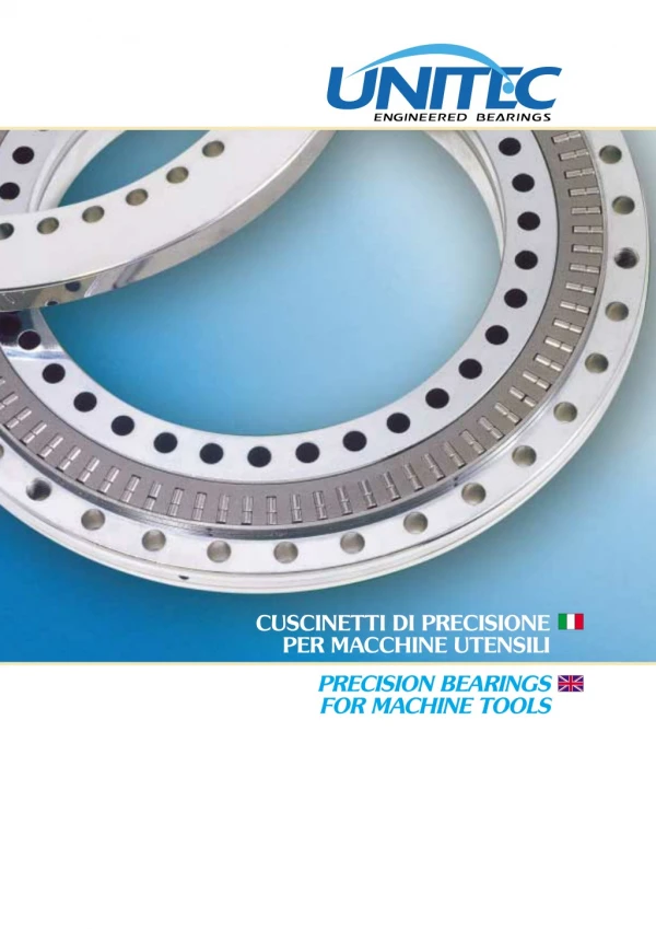
CUSCINETTI DI PRECISIONE PER MACCHINE UTENSILI PRECISION BEARINGS FOR MACHINE TOOLS
Indice Contents RTB Cuscinetti assiali-radiali a rulli, per tavole di indexaggio Combined axial-radial roller bearing for indexing tables • Specifiche tecniche Technical specifications • Tabella cuscinetti RTB RTB bearings tables RTB AMS Cuscinetti assiali-radiali a rulli, con encoder induttivo integrato Combined axial-radial roller bearing, with integrated inductive encoder • Specifiche tecniche Technical specifications • Tabella cuscinetti RTB AMS RTB AMS bearings tables SRB Cuscinetti a rulli e rullini per viti a ricircolo di sfere Needle and roller bearings for screw drives • Descrizione e specifiche Description and specifications • Tabella cuscinetti SRB SRB bearings table • Tabella cuscinetti SRB_L - con ralla porta tenuta SRB_L bearings table - with extended washer • Tabella cuscinetti SRB_F - con flangia di fissaggio SRB_F bearings tabel - with fixing flange • Tabella cuscinetti SRB_FL - con flangia di fissaggio e ralla porta tenuta SRB_FL bearings table - with fixing flange and extended washer • Tabella cuscinetti SRB_T - con fori di fissaggio SRB_T bearings table - with fixing holes Ghiere di precisione MONDIAL MONDIAL precision locknuts • HIF Bloccaggio laterale Side locking • HIA Bloccaggio assiale Axial locking • HIR Bloccaggio radiale Radial locking • Selezionatura ghiere Locknuts selection XRB Cuscinetti customizzati a rulli incrociati Customized cross roller bearings • Esempi Examples Disegni speciali customizzati Custom special drawings PAG. 8 PAG. 9 PAG. 18 PAG. 20 PAG. 20 PAG. 24 PAG. 26 PAG. 26 PAG. 28 PAG. 30 PAG. 32 PAG. 34 PAG. 36 PAG. 38 PAG. 39 PAG. 40 PAG. 41 PAG. 42 PAG. 44 PAG. 46 PAG. 47
componenti meccanici innovativi Mondial, Azienda leader nell’importazione e commercializzazione di componenti meccanici innovativi e di elevata qualità, offre un servizio costantemente adeguato alle esigenze del mercato. Un servizio che integra dinamicamente l’organizzazione commerciale con quella tecnica e logistica, proponendo una completa gamma di organi di trasmissione, provenienti da tutto il mondo, competitivi e all’avanguardia. Mondial è una Azienda certificata ISO 9001:2000. innovative power transmission components Mondial is a leading company in the import and distribution of power transmission components. Mondial always provides its customers with highly qualified products matched with an excellent logistical and technical support. Mondial is an ISO 9001:2000 certified Company. 4
CUSCINETTI DI PRECISIONE PRECISION BEARINGS UNITEC, azienda leader nella progettazione e costruzione di cuscinetti speciali di precisione a rulli cilindrici per macchine utensili e per altre applicazioni industriali, offre ai suoi clienti in tutto il mondo un servizio di elevata qualità: assistenza tecnica qualificata sin dalle prime fasi del progetto, una rete commerciale capillare, un servizio postvendita affidabile, costantemente adeguato alle esigenze del mercato. UNITEC fa parte del Gruppo Mondial ed è un’azienda certificata ISO 9001:2000 e ISO 14001:2004. UNITEC, leading company in the design and manufacturing of special precision cylindrical roller bearings for machine tools and general industry, delivers high quality service and support to customers world-wide. Engineering partnership, technical and logistic services and our commercial network, supplied by different distribution channels, allows us to fulfil unique application requirements on the marketplace. UNITEC is a certified ISO 9001:2000 and ISO 14001:2004 company, belonging to Mondial S.p.A. Group. 5
tecnologia avanzata Tecnologia avanzata per soddisfare le esigenze di progetto dei vostri clienti. Ingegneri e progettisti vi assisteranno nella selezione del cuscinetto UNITEC più idoneo per le vostre nuove applicazioni e per la scelta del montaggio più appropriato. advanced technology Advanced technology to meet your customers requirements. Our engineers will assist you in selecting the most suitable UNITEC bearing and mounting arrangement for your applications. 6
alti livelli di produttività CUSCINETTI DI PRECISIONE I vostri clienti vi richiedono macchine utensili che siano precise, affidabili e che possano garantire i più alti livelli di produttività. PRECISION BEARINGS Il cuscinetto di precisione UNITEC è il cuore della vostra macchina. Your customers require highly precise and reliable machine high productivity tools able to secure high productivity. UNITEC precision bearing is the heart of your machine. 7
RTB elevata rigidezza ed elevata precisione Cuscinetti assiali-radiali a rulli, per tavole di indexaggio Combined axial-radial roller bearing for indexing tables Cuscinetti assiali-radiali di precisione per tavole di posizionamento e indexaggio. high rigidity together with high accuracy L’elevata rigidezza assiale e la capacità di sopportare elevate coppie di ribaltamento rende questo cuscinetto UNITEC serie RTB particolarmente adatto all’impiego nelle tavole rotanti,di posizionamento e di indexaggio teste fresa. Axial-radial precision bearings for indexing tables. Due to their high axial stiffness and their capacity to bear high tilting moments, UNITEC bearings RTB series are particularly recommended for rotating, positioning and indexing tables and milling heads. 8
Specifiche tecniche Technical specification 1. Descrizione 2. Rigidezza 3. Indicazioni per il montaggio 4. Precarico 5. Attrito 6.Velocità 1. Description 2. Stiffness 3. Mounting instructions 4. Preload 5. Friction 6. Operating speed 1. Descrizione I cuscinetti della serie RTB sono costituiti da un anello interno sagomato (profilo ad L), integrato con una ralla di chiusura, da un anello esterno, da due gabbie assiali a rulli e da un pieno riempimento radiale a rulli. I valori delle capacità di carico assiali e radiali sono stati calcolati secondo le norme UNI ISO 76 e UNI ISO 281 utilizzando coefficienti adeguati all’elevata qualità degli acciai impiegati ed ai trattamenti termici specifici eseguiti. Alle norme su menzionate ed ai relativi aggiornamenti/integrazioni, si prega di riferirsi anche per il calcolo della durata. I cuscinetti RTB vengono forniti in due configurazioni base: • Non lubrificato – RTB Il cuscinetto è avvolto in carta oleata totalmente ricoperto da film di olio protettivo. In questo caso, deve essere previsto da parte dell’utilizzatore un’adeguata lubrificazione ad olio o a grasso. I cuscinetti sono provvisti di fori radiali sull’anello interno ed esterno per consentire l’apporto di lubrificante. • Lubrificato a grasso – RTB_G Il cuscinetto viene prelubrificato con grasso ai saponi di litio, EP, NLGI 2, 150 cst a 40°C con un riempimento di circa il 50 %. Per richiesta di utilizzo di grassi diversi, si suggerisce di prevedere le configurazioni non lubrificate e procedere al caricamento del grasso specifico tramite gli appositi fori. 2. Rigidezza Elevata rigidezza, grande capacità di carico, elevata precisione di rotazione, sono i requisiti fondamentali dei cuscinetti assiali – radiali UNITEC serie RTB. L’impiego di gabbie assiali ad elevato numero di corpi volventi, con contatto lineare, contribuisce ad ottenere un movimento preciso e rigido, così come l’elevatissima precisione delle lavorazioni meccaniche. Le dimensioni dei rulli, sia assiali che radiali, e degli anelli interno ed esterno sono calibrate in modo tale che al serraggio delle viti di fissaggio si ottengano i precarichi previsti. Le tolleranze, imposte in produzione, del valore dei precarico sono particolarmente ristrette così da garantire un’elevata costanza ed uniformità di fornitura nel tempo. Grazie al precarico ed al contatto lineare dei corpi volventi, la rigidezza assiale, radiale ed a ribaltamento dei cuscinetti RTB può considerarsi, con buona approssimazione, una grandezza lineare (andamento quasi lineare delle curve di rigidezza), per cui, i rispettivi valori Ka, Kr e Kmr, possono essere assunti come costanti e riportati come tali nella relativa tabella dimensionale (Tab. 1). Questi valori sono stati determinati con calcoli agli elementi finiti (FEM) mediante opportuna modellazione del cuscinetto assiale – radiale, relativamente alle diverse taglie, nelle due diverse condizioni di montaggio illustrate in Fig. 1 e Fig. 2. Al riguardo, si riportano le Fig. 3 e 4 quale esempio degli stati tensionali indotti nei cuscinetti RTB, nei due casi, rispettivamente. 1. Description RTB bearings consist of a moulded inner ring (L section) – completed with a washer -, an outer ring, two roller thrust bearings and a cylindrical roller bearing, full complement. The axial and radial load-carrying capacity have been calculated according to UNI ISO 76 and UNI ISO 281 standard, by using factors suitable for the high quality steels and the specific heat treatments connected with these bearing series. As for the life calculation, also refer to the a.m. standard. RTB bearings are available in two different designs: • RTB - without lubrication The bearing is wrapped in oil-paper, completely covered with a protective oil film. Customer must provide for an adequate oil or grease lubrication. For this purpose, bearings have radial holes on the inner and outer rings. • RTB_G – with grease lubrication The bearing is pre-lubricated with (litium based grease, EP, NLGI 2, 150cst at 40 Celsius deg) – approx. 50% filling. If a different grease is requested, we suggest to ask for a non lubricated design and then to fill with the requested grease through the lubrication hole. CUSCINETTI DI PRECISIONE PRECISION BEARINGS 2. Stiffness High stiffness, considerable load-carrying capacity, high rotational accuracy are the essential features of the combined UNITEC RTB bearings.The axial cages with a big number of rolling elements with linear contact as well as the very high precision of the machining permit a precise and rigid movement. The size of the axial and radial rollers as well as of the inner and outer rings are carefully measured in order to obtain the requested preloads by tightening the cap screws.The manufacture tolerances of the preload value are particularly restricted, so that a constant and uniform quality of the supplies can be granted over the years.Thanks to the preload and the linear contact of the rolling elements, the axial, radial and tilting stiffness of the RTB bearings can be considered, at a rough estimate, a linear magnitude (almost linear trend of the stiffness curves), so that the relevant values Ka, Kr and Kmr can be assumed as a constant and stated as such in the concerning dimensional table (Tab. 1). The a.m. values have been obtained by means of FEM calculations, by modelling the different sizes of the combined bearing according to the two different assembly layouts (see Pics 1 and 2). In Pics 3 and 4 you can see a typical induced stress in the RTB bearings, according to the two different assembly layouts. 9
Appendice tecnica Technical abstract RTB Mr = tilting moment Ax = axial load Rd = radial load 1 Schema di montaggio senza ralla di supporto Assembly layout without thrust washer 2 Schema di montaggio con ralla di supporto Assembly layout with thrust washer 3 Stato tensionale senza ralla di supporto Static nodal stress without thrust washer 4 Stato tensionale con ralla di supporto Static nodal stress with thrust washer 10
Tab. 1 TABELLA VALORI DI RIGIDEZZA STIFFNESS VALUE (**) con ralla di supporto With thrust washer senza ralla di supporto Without thrust washer Diametro foro del cuscinetto Bore diameter (mm) Rigidezza assiale Axial stiffness Rigidezza a momento ribaltante Tilting stiffness KMR (kNm/mrad) Rigidezza assiale Axial stiffness Rigidezza a momento ribaltante Tilting stiffness KMR (kNm/mrad) Rigidezza radiale Radial stiffness Sigla Designation CUSCINETTI DI PRECISIONE KAX KAX KRD (kN/µm) (kN/µm) (kN/µm) 80 100 120 150 180 200 260 325 395 460 RTB 80 RTB 100 RTB 120 RTB 150 RTB 180 RTB 200 RTB 260 RTB 325 RTB 395 RTB 460 1,9 2,4 3,2 4,0 4,9 5,5 8,3 9,5 13,1 16,0 1,7 3,7 7,6 12,5 20 27,6 51,5 88,5 158,1 218,5 2,4 2,0 2,6 3,3 2,9 2,9 5,7 6,0 5,9 6,3 1,8 2,3 3,0 3,7 4,3 4,9 8,1 9,2 11,5 13,6 1,6 3,3 6,5 10,9 17,1 24,3 48,4 81,3 148,5 209,1 PRECISION BEARINGS (°) I valori di rigidezza indicati tengono conto delle deformazioni di tutti i componenti del cuscinetto montato mediante collegamento con le viti di serraggio previste. Sono possibili scostamenti rispetto ai valori reali, relativi al grado di approssimazione del modello rispetto al sistema reale. (°) A. m. stiffness values consider the deformation of all components of the bearing (assembled with cap screws). Deviations from the actual values are possible, according to the approximation of the model with respect to the real system. (**) As for the radial stiffness values, the differences between the two assembly schemes are insignificant. (**) Per i valori di rigidezza radiale, non si apprezzano significative variazioni nel passaggio da uno schema di montaggio all’altro. 11
RTB 3. Indicazioni per il montaggio Per il montaggio si suggerisce di rispettare le prescrizioni indicate nello schema riportato in Fig. 5. 3. Mounting instructions For mounting instructions we recommend to follow specifications reported in Pic 5. 5 Indicazioni di montaggio Mounting instructions 12
4. Precarico L’applicazione del precarico nei cuscinetti nasce fondamentalmente dall’esigenza di avere un aumento di rigidezza e di precisione della rotazione. In presenza di un carico esterno, precaricare il cuscinetto significa recuperare o evitare il giuoco che si originerebbe in corrispondenza del cedimento elastico dovuto al carico stesso. Le deformazioni elastiche provocate dal carico, sono, in tal caso, per un dato campo di carichi, minori che nel cuscinetto non precaricato. Assumendo che la caratteristica di rigidezza sia lineare (contatto di rulli su piste), lo spostamento assiale in un sistema precaricato di cuscinetti è inferiore a quello in un sistema non precaricato, a parità di carico assiale (vedi Fig. 6, carico Fx). La Fig. 6 illustra i due casi. La linea (1) rappresenta la caratteristica di cedimento elastico di un sistema (ad esempio di due cuscinetti assiali uguali A e B) montato non precaricato, sottoposto ad un carico esterno Fx. La linea (2), quello dello stesso sistema assemblato con un precarico pari al valore Fo. Nel caso del sistema precaricato (linea 2), l’applicazione del carico assiale esterno Fx, carica il cuscinetto A e scarica B di un valore corrispondente a Fx/2, mentre nel caso senza precarico (linea 1), la stessa situazione comporta che il carico esterno Fx venga integralmente supportato dal cuscinetto A con distacco del contatto di B. In conclusione, la rigidezza assiale di un sistema precaricato è doppia. Aumentare il valore di precarico con i cuscinetti RTB non aumenta la rigidezza ma semplicemente sposta il limite del distacco a valori di forza Fx più elevati. In altre parole, se la forza assiale esterna supera un valore pari a due volte quello del precarico (Fx > 2Fo), il cuscinetto B si scarica completamente e la rigidezza assiale del sistema è unicamente determinata dal cuscinetto A, come nel caso di cuscinetti montati senza precarico, però lo spostamento assiale nel caso (2), in quest’ultima situazione, rimane comunque inferiore rispetto al caso (1) (vedi Fig. 6). 4. Preload The preload of the bearings increases the stiffness and the rotational accuracy. In presence of a load from the outside, the preload of the bearing eliminates or avoids the backlash corresponding to the elastic yielding due to the load itself. In this case, for a given range of loads, the elastic deformations caused by the load are smaller than in a non-preloaded bearing. Assuming the stiffness is linear (rollers in contact with tracks), at the same axial load the axial deflection is smaller in a preloaded bearings system than in a non- preloaded system (see Pic 6, load Fx). In Pic 6 the two different situations are represented. Line no. 1 represents the elastic yielding of a non- preloaded system (for instance of two similar axial bearings A) and B), put through the outside load Fx. Line no. 2 refers to the same system assembled with preload equal to value Fo. As for the preloaded system (line no. 2), the outside axial load Fx charges bearing A and discharges bearing B with a value corresponding to Fx/2. As for the non-preloaded system (line no. 1), the outside axial load Fx is fully borne by bearing A with loss of contact of bearing B. To sum up, the axial stiffness of a preloaded system is twice as much. As for the RTB bearings, to increase the preload value doesn’t increase the stiffness but simply shifts the disconnection point to higher force values Fx. In other words, if the axial force from the outside exceeds a value equal to twice the preload value (Fx>2Fo), the bearing B is fully discharged and the axial stiffness of the system is entirely determined by bearing A (as for non-preloaded bearings) but the axial deflection in case (2), as for the last situation, is shorter than in case (1) (see Pic 6). CUSCINETTI DI PRECISIONE PRECISION BEARINGS 2 Fx 1 Fx=2Fo (1) sistema senza precarico system without preload (2) sistema con precarico Fo system with preload Fo Fx = forza assiale esterna external axial force δ = spostamento assiale axial deflection δ δ con prec. with prel. δ con senza prec. without prel. 6 13
RTB 5. Attrito Nei cuscinetti la resistenza complessiva al moto dipende da molti fattori, i più importanti dei quali sono: o precarico o viscosità e quantità del lubrificante o carico applicato o dimensione del cuscinetto o velocità di rotazione 5. Friction As for the bearings, the friction depends on many factors, the most important of which are: o preload o viscosity and amount of the lubricant o applied load o bearing size o rpm Più in dettaglio: • Un precarico maggiore porta ad una coppia di rotolamento superiore • Nei cuscinetti RTB si suggerisce di rispettare i seguenti valori relativi alle coppie di serraggio delle viti di fissaggio: That is: • A bigger preload turns out in a bigger rolling friction torque. • As for the RTB bearings, we suggest to respect following tightening torque values (which are the max values for bolt class 8.8): M5 M6 M8 6,1 Nm 10,4 Nm 25 Nm Si rititene importante ricordare che con la serie RTB (versioni standard), il serraggio delle viti dell’anello interno comporta l’annullamento dei giochi assiali dimensionali o interni e la compressione elastica dell’anello interno • Cuscinetti appena ingrassati, sono caratterizzati da momenti d’attrito più elevati. • Una buona distribuzione del grasso o una lubrificazione ad olio ottimale risulta determinante al fine di ottenere un basso valore del momento d’attrito. We remind you that as for the RTB bearings (standard types), the fixing of the inner ring screws involves the annulment of the dimensional or inner axial backlash as well as the elastic compression of the inner ring. • Newly greased bearings have higher friction torques. • A good grease distribution or an ideal oil lubrication is decisive to obtain a lower friction torque. The friction torque values of the various RTB bearing designs (see Tab. 2) are obtained in the following test conditions: I valori della coppia d’attrito per le diverse tipologie di cuscinetti RTB, riportati in Tab. 2, sono ottenuti con prove di funzionamento nelle seguenti condizioni: 1.montaggio tipo con ralla di supporto (vedi Fig.2). In assenza di anello di supporto, nelle taglie più piccole, si possono ottenere coppie di rotolamento inferiori. 2.Lubrificazione a grasso Grasso ai saponi di litio, EP, NLGI 2, 150 cst a 40°C. 3.Velocità di rilevamento: 5rpm. Il valore indicato include l’eventuale spunto che in genere è inferiore al 10% del valore costante. 4.Temperatura di prova: 30÷40°C. 1.Assembly with thrust washer (see Pic 2). Failing the thrust ring, in the smaller sizes, it is possible to obtain lower rolling resistance moments. 2.Grease lubrification Litium based grease, EP, NLGI 2, 150cst at 40 Celsius deg. 3.Operating speed: 5 rpm A.m. value includes the starting frictional torque (as a rule the starting torque is lower than 10% of the even value). 4.Test temperature: 30°÷40°C 14
Tab. 2 (°) sigla Diametro foro del cuscinetto Bore diameter (mm) Coppia rotolamento Rolling torque CRL(Nm) Designation 80 100 120 150 180 200 260 325 395 460 RTB 80 RTB 100 RTB 120 RTB 150 RTB 180 RTB 200 RTB 260 RTB 325 RTB 395 RTB 460 2 2 8 10 13 15 19 21 25 30 CUSCINETTI DI PRECISIONE PRECISION BEARINGS (°) I valori riportati sono statistici e quindi sono da considerarsi indicativi The a.m. values are to be intended as statistical 15
RTB 7 In Fig. 7 e in Fig. 8 si riportano i diagrammi relativi alla coppia di rotolamento, ottenuta a 5rpm per l’RTB395 e l’RTB120 rispettivamente. Si noti come il picco di spunto sia assolutamente trascurabile. Pic 7 and Pic 8 report the rolling torque charts at 5 rpm of the RTB 395 and RTB 120. Note that the starting torque peak is negligible. 8 16
Designazione cuscinetti RTB RTB bearings P/N designation Suffisso / Suffix: G = cuscinetto ingrassato / greased bearing P = super preciso (metà runout assiale e radiale) super precision (half axial & radial runout) RTB_x y z k = P/N disegno speciale customizzato custom drawing P/N CUSCINETTI DI PRECISIONE Esempi / Examples: RTB 460 GP • diametro interno 460 mm / 460 mm bore • cuscinetto ingrassato / greased bearing • super preciso (metà runout assiale e radiale) super precision (half axial & radial runout) i.e. 3 µm PRECISION BEARINGS RTB 325 - 0648 • diametro interno 325 mm / 325 mm bore • fornito con olio protettivo / supplied with protective oil • disegno customizzato 0648 / custom drawing 0648 6.Velocità di rotolamento (rpm) - Operating speed (rpm) Tipo Lubrificazione Lubrification RTB 80 RTB 100 RTB 120 RTB 150 RTB 180 RTB 200 RTB 260 RTB 325 RTB 395 RTB 460 Grasso Grease 420 330 270 250 230 200 160 130 110 100 Olio Oil 870 700 570 520 470 420 320 270 220 200 Le velocità riportate sono da considerarsi limiti per regime continuativo o come velocità medie per funzionamento intermittente con velocità di punta superiori fino al 40% d’incremento. Si rammenta che la viscosità minima del lubrificante in esercizio è determinante per il calcolo dei fattori correttivi della durata, come da norme ISO. The a.m. operating speeds shall be considered as limiting speeds in case of continuous working or as average speeds in case of intermittent working with peak speeds exceeding additional 40% . We remind that the lubricant minimum viscosity is decisive to calculate the life remedial factor according to ISO. 17
RTB CUSCINETTI ASSIALI-RADIALI A RULLI, PER TAVOLE DI INDEXAGGIO COMBINED AXIAL/RADIAL ROLLER BEARING FOR INDEXING TABLES N° dis. lub. a olio Part Number oil lub. N° dis. lub. a grasso Ø tavola Part Number grease lub. n° sedi Fixing holes n° d D mm B mm H mm b D1 mm J J1 mm d1 mm d2 mm a Suitable table Ø mm mm mm mm RTB 80 RTB 100 RTB 120 RTB 150 RTB 180 RTB 200 RTB 260 RTB 325 RTB 395 RTB 460 RTB 80 G RTB 100 G RTB 120 G RTB 150 G RTB 180 G RTB 200 G RTB 260 G RTB 325 G RTB 395 G RTB 460 G 1000 200 260 315 350 400 500 630 700 800 80 100 185 38 120 210 40 150 240 40 180 280 43 200 300 45 260 385 55 325 450 60 395 525 65 460 600 70 146 35 23,35 12 130 160 112 170 184 135 195 214 165 225 244 194 260 274 215 285 345 280 365 415 342 430 486 415 505 560 482 580 92 138 5,6 5,6 7 7 7 7 9,3 9,3 9,3 9,3 10 10 11 11 11 11 15 15(3) 15 15 4 12 15 21 33 45 45 34 34 46 46 25 26 26 29 30 36,5 40 42,5 46 12 12 12 15 15 18 20 20 22 5,4 6,2 6,2 6,2 6,2 8,2 8,2 8,2 8,2 (1) Viti di trattenuta posizionate tra le sedi d2 (2) Viti di trattenuta avvitate nelle ralle (3) Lamature aperte verso l’interno 18
TOLLERANZE SECONDO CLASSE DI PRECISIONE P4 / P2 DIMENSIONAL TOLERANCE ACCORDING TO PRECISION CLASS P4 / P2 CUSCINETTI DI PRECISIONE PRECISION BEARINGS Coeff. di carico ISO Load ratings according to Errore assiale e radiale di rotazione Axial and radial runout µ V. max. ad olio Max speed oil rpm V. max. grasso Max speed grease rpm RADIALE RADIAL ASSIALE AXIAL N° dis. lub. a olio Part Number oil lub. N° dis. lub. a grasso Part Number grease lub. n° viti di trattenuta Fixing screws n. din. C dyn. C kN stat. Co stat. Co kN din. Ca dyn. Ca kN stat.Coa stat.Coa kN d3 mm G n°×α° n°d3 n°G RTB 80 RTB 100 RTB 120 RTB 150 RTB 180 RTB 200 RTB 260 RTB 325 RTB 395 RTB 460 RTB 80 G 4,6 RTB 100 G 5,6 RTB 120 G RTB 150 G RTB 180 G RTB 200 G RTB 260 G 9,3 RTB 325 G 9,3 RTB 395 G 9,3 RTB 460 G 9,3 12 15 21 33 45 45 33 33 45 45 3(1) 3 3 3 3 3 2(2) 2(2) 2(2) 2(2) / / 3 3 3 3 3 3 3 3 3 3 3 3 3 4 4 6 6 6 6 45,3 56,4 71,9 83,3 88,5 135,4 137,9 480,3 151,1 173,6 699,5 210,1 106,8 128,5 174,5 210,8 109,7 664,1 274,2 125,7 826,4 297,2 103,6 125,9 935,9 581,4 216,9 1768,9 235,6 2085,8 807,9 260,2 55,4 97,8 108,5 614,9 269,4 509,8 870 700 570 520 470 420 320 270 220 200 420 330 270 250 230 200 160 130 110 100 12x30° M5 M8 M8 M8 M8 M12 M12 M12 M12 18x20° 7 7 7 7 24x15° 36x10° 48x7,5° 668 48x7,5° 36x10° 36x10° 48x7,5° 2467 48x7,5° (1) Fixing screws are between d2 holes (2) Fixing screws are screwed into rings (3) Milled slots open towards bearing bore 19
RTB AMS Cuscinetti assiali-radiali a rulli, con encoder induttivo integrato Combined axial-radial roller bearings, with integrated inductive encoder Specifiche tecniche Technical specification IDEALI PER MOTORI DIRETTI IDEAL FOR DIRECT DRIVES I cuscinetti UNITEC tipo RTB AMS con sistema di misura angolare integrato sono combinati assiali radiali a doppio effetto studiati per il supporto di tavole rotanti e teste di mandrini per macchine utensili. UNITEC RTB AMS bearings series, with integrated angle measuring system are bidirectional axial-radial combined, designed for rotary tables and spindle heads for machine tools. Per migliorare le prestazioni delle applicazioni per le quali sono previsti i cuscinetti RTB, UNITEC ha sviluppato la versione RTB AMS che integra il sistema di misura angolare di precisione AMOSIN. La precisione costruttiva (secondo classe di precisione P4/P2), i bassi livelli di coppia resistente, l’elevata capacità di carico e rigidezza li pongono nel mercato ai massimi livelli di qualità e li rendono adatti a supportare installazioni su cui sono previsti motori coppia diretti. To improve performances of applications where RTB bearings series are installed, UNITEC developed new version RTB AMS, integrating AMOSIN precision inductive measuring system. The manufacturing precision (class P4/P29, low resistant torque, high load capacity and stiffness are positioning this bearings range at the top of the market, qualifying them as the most suitable solution for direct drive installations. 20
CARATTERISTICHE DEI CUSCINETTI UNITEC RTB AMS UNITEC RTB AMS BEARINGS FEATURES • SISTEMA A SCANSIONE INDUTTIVA (NON MAGNETICO) • ASSOLUTA INSENSIBILITA’ AI CAMPI MAGNETICI • SEGNALI D’USCITA IN TEMPO REALE, (IDEALE PER MOTORI DIRETTI) • ELEVATA VELOCITA’ DI ROTAZIONE • ELEVATA RISOLUZIONE E PRECISIONE • INDUCTIVE MEASURING SYSTEM (NON MAGNETIC) • INSENSITIVITY TO MAGNETIC FIELDS • REAL TIME OUTPUT SIGNALS (IDEAL FOR DIRECT DRIVES) • HIGH ROTATION SPEED • HIGH MEASURING RESOLUTION AND ACCURACY CUSCINETTI DI PRECISIONE PRECISION BEARINGS Inoltre: • Soluzione compatta. Moreover: • The most compact solution. • Insensibilità agli agenti esterni. (sensori protetti IP 67) • Insensitivity to external agents (IP 67 protected sensors) • Installazione semplice. • Simple installation. • Taratura veloce. • Quickest setting. • Funzionamento stabile ed affidabile. • Nessun software di settaggio necessario. • Stable and reliable functioning. • No setting software needed. Il sistema è fornibile in configurazioni customizzate a richiesta, con diversi livelli di precisione e risoluzione. The system is available in custom configurations, with different precision and resolution level 21
RTB AMS CARATTERISTICHE DEL SISTEMA DI MISURA INDUTTIVO INDUCTIVE ANGLE MEASURING SYSTEM FEATURES • Scala graduata in classe di precisione +/-5 µm • Indici di riferimento.Versione standard: un indice di riferimento su 360° Versione a richiesta: vari indici di riferimento su 360° a distanza codificata • Segnali d’uscita sinusoidali 1 Vpp (resist.Terminale 120W) secondo standard mercato (segnali in onda quadra TTL a richiesta) • Vari fattori di interpolazione (vedi Tab. 3) • Accuratezza totale fino a +/- 3” di grado (cuscinetti di massima taglia) • Measuring scale available in precision class: +/-5 µm • Reference marks (zero). Standard version: one reference mark on 360°. Optional reference: several distance-coded reference marks on 360° upon request. • Output signals 1 Vpp (for term. resistance 120 Ω) - optional TTL square wave upon request • Several interpolation factors in order to adjust the resolution of the system as needed (check Tab. 3) • Total accuracy of the system up to +/- 3” of arc (max bearing size) Valori di risoluzione - Resolution values Diam. foro Bore dia. P/N N° di periodi base N° of basic periods (T/giro) (T/rev) N° di periodi con fatt. 1/32 N° of basic periods with factor 1/32 (T/giro) (T/rev) (mm) 150 180 200 260 325 395 460 RTB 150 AMS RTB 180 AMS RTB 200 AMS RTB 260 AMS RTB 325 AMS RTB 395 AMS RTB 460 AMS 672 768 864 1088 1296 1512 1752 21504 24576 27618 34816 41472 48384 56064 Tab. 3 T = Periodo sinusoide T = Sinewave period Grazie all’elevata modularità del sistema ed alla sua completezza, siamo in grado di calibrare la fornitura secondo le esigenze della clientela: Thanks to the modularity of the system, we can tailor the proposal in order to fulfil customer specific requirements: • CONFIGURAZIONE AD ALTA RISOLUZIONE (scala graduata in classe +/- 5 µm, 1 testina di lettura, fattore interpolazione 1/32). Quando l’accuratezza richiesta al sistema di misura non è esasperata • HIGH RESOLUTION CONFIGURATION (precision scale +/- 5µm, 1 measuring head, interpolation factor 1/32) when requirements are not for extremely high accuracy. • CONFIGURAZIONE AD ALTA RISOLUZIONE E AD ALTA PRECISIONE (scala graduata in classe +/-5 µm, 2 testine di lettura, fattore interpolazione 1/32) La massima prestazione sia come precisione che risoluzione. • HIGH RESOLUTION AND HIGH PRECISION CONFIGURATION (precision scale +/- 5 µm, 2 measuring heads, interpolation factor 1/32) for maximum performances in accuracy and resolution. 22
Il sistema di misura AMOSIN: AMOSIN measuring system: ? esclusivamente induttivo. ? is purely inductive. ? precisione paragonabile ai corrispondenti sistemi di misura optoelettronici. Alta qualità del segnale con deviazione della precisione della sinusoide inferiore a 0.1%. ? achieves degrees of accuracy up to the optoelectronic systems. High quality of the output signal with sinusoidal accuracy deviations lower than 0.1%. ? is extremely protected from environmental pollution such as solid particles, grease, oil etc. CUSCINETTI DI PRECISIONE ? estremamente resistente verso le condizioni ambientali critiche, come particelle solide, olio, etc. ? is extremely high shock and vibration resistant. ? alta resistenza alle sollecitazioni meccaniche come shock e vibrazioni. ? generates two sine wave signals with a period of 1000 µm (interpolation factor 1/19 referred to an arc length of the flange circumferential surface. ? periodo base dei segnali sinusoidali di 1000 µm relativo alla graduazione della scala graduata e riferito ad un pari arco della circonferenza della flangia su cui è avvolta. PRECISION BEARINGS ? is provided with interpolation factor 1/32, which allow to reduce the period length down to approx. 30 µm, with low noise/signal ratio. ? fattore di interpolazione standard 1/32 che permette di ridurre la lunghezza del periodo fino a circa 30 µm con ottimo rapporto segnale/ rumore. Suddivisione del segnale sinusoidale di periodo λ=1 mm Subdivision of the sinewave signal with period λ=1 mm 23
RTBAMS CUSCINETTI ASSIALI-RADIALI A RULLI, CON ENCODER INDUTTIVO INTEGRATO COMBINED AXIAL-RADIAL ROLLER BEARINGS,WITH INTEGRATED INDUCTIVE ENCODER D D2 J d d1 2 3 F b B h d2 a D1 J1 Dimensioni di ingombro estremamente contenute Extremely compact design Le quote riportate in tabella sono relative agli ingombri delle testine di misura, in particolare quelle contrassegnate con * differiscono dalle quote dei cuscinetti standard per l’aumentato spessore della flangia. The dimensions indicated in the table below refer to the sensor heads integration. Sizes marked with * differ from relative standard RTB bearings, because of the increased flange thickness. Diam. foro d Bore diam. Suitable tableø øDiam. tavola J J1 d1 d2 D2 B H b D1 D L F P/N cuscinetto Bearing P/N mm mm mm mm mm mm mm mm mm mm mm mm mm RTB 150 AMS RTB 180 AMS RTB 200 AMS RTB 260 AMS RTB 325 AMS RTB 395 AMS RTB 460 AMS 150 180 200 260 325 395 460 350 400 500 630 700 800 1000 240 280 300 385 450 525 600 43* 46* 47* 55 60 65 70 26 29 30 36.5 40 42.5 46 12 15 15 18 20 20 22 214 244 274 345 345,5 415 415,5 486 486,5 560 560,5 215 245 274 165 194 215 280 342 415 482 225 260 285 365 430 505 580 16,5 16,5 16,5 17,5 18,5 18,5 18,5 120 135 150 186 219 254 292 7 7 7 11 11 11 15 15(3) 15 15 9.3 9.3 9.3 9.3 24
Gx3 d3 α° CUSCINETTI DI PRECISIONE 1 sensore o 2 sensori a 180° 1 sensor or 2 sensor at 180° 34 16 PRECISION BEARINGS L Sistema di misura a scansione induttiva AMOSIN measuring system Precisione Alta Precision High Velocità di rotazione Alta Rotation speed High Sensibilità alla presenza di polveri, oli, grassi Resistente Sensitivity to grease, oil, dust Resistant Sensibilità a particelle ferrose o magnetiche Resistente Sensitivity to steel and magnetic grains Resistant Sensibilità a campi elettromagnetici Resistente Sensitivity to magnetic interference fields Resistant Sensibilità a shock e vibrazioni Resistente Resistance to shock and vibrations Resistant Sensibilità ad escursioni termiche Bassa Sensitivity to temperature variation Low Coefficienti di carico sec. Load ratings according to ISO Errore assiale e radiale di rotazione Axial and radial runout µm Velocità max lubrificazione a olio Max speed oil Velocità max lubrificazione a grasso Max speed grease ASSIALE AXIAL RADIALE RADIAL N° viti di trattenuta Fixing holes n° Fixing screws n° Nr.d3 Nr. a d3 G α° Din kN Ca Din kN C Stat. kN Co Stat. kN Cao mm G mm mm N° sedi rpm rpm 6.2 6.2 6.2 8.2 8.2 8.2 8.2 33 45 45 34 34 46 46 7 7 7 33 45 45 33 33 45 45 3 3 3 M8 M8 M8 M12 M12 M12 M12 3 3 3 3 3 3 3 36x10° 48x7.5° 48x7.5° 36x10° 36x10° 48x7.5° 48x7.5° 3 4 4 6 6 6 6 80.2 85 135.4 134 147 168 204 201 262 297.2 463 561 675 780 101 116.3 103.6 116 202 219 242 633 791 668 896 1712 2013 2388 520 470 420 320 270 220 200 250 230 200 160 130 110 100 9.3 9.3 9.3 9.3 2(2) 2(2) 2(2) 2(2) 25
SRB evoluzione tecnologica Cuscinetti a rulli e rullini per viti a ricircolo Needle and roller bearings for screw drives technology evolution L’evoluzione tecnologica permette il raggiungimento di velocità di taglio sempre più elevate pur nel mantenimento del livello di precisione richiesto per ogni specifica applicazione. I cuscinetti radiali a rullini combinati con cuscinetti assiali a rulli cilindrici UNITEC serie SRB migliorano la rigidezza statica e dinamica delle vostre viti a ricircolo di sfere. Advanced technology allows to reach very high cutting speeds while securing the precision level requested for each application. UNITEC SRB combined bearings enhance static and dynamic stiffnessof your ballscrews.. Descrizione e specifiche I cuscinetti della serie SRB sono composti da un cuscinetto radiale a rullini caratterizzato da un anello esterno massiccio ed un anello interno prolungato. Le superfici laterali dell’anello esterno fungono da piste di rotolamento per le due gabbie assiali. Sull’anello interno avviene poi il centraggio delle due gabbie assiali. Tale forma costruttiva permette di realizzare con minimo ingombro un supporto preciso e perfettamente rigido. I cuscinetti SRB sono stati studiati, nelle varie versioni costruttive, per supporto assiale radiale delle viti di precisione a ricircolo di sfere, utilizzate prevalentemente sulle macchine utensili. Per ottenere la massima rigidezza tali cuscinetti vengono precaricati tramite ghiera di precisione. 26
Description and specifications SRB series bearings consist of a needle roller radial bearing with solid outer ring and an extended inner ring.The side surfaces of the outer ring act as tracks for the two axial cages.The two axial cages are centered on the inner ring. Thanks to this design it is possible to realize a precision journal, having little overall dimensions and high stiffness. All SRB bearing designs have been developed in order to be a radial/axial support for precision ball screws of machine tools. In order to obtain max stiffness, these bearings are preloaded by means of a locknut. CUSCINETTI DI PRECISIONE PRECISION BEARINGS Designazione cuscinetti SRB SRB bearings P/N designation SRB dD SRB dD F SRB dD T SRB dD L SRB dD FL 27
SRB RADIALI A RULLINI COMBINATI CON ASSIALI A RULLI CILINDRICI RADIAL NEEDLE ROLLER COMBINED WITH AXIAL CYLINDRICAL ROLLER TABELLA DIMENSIONALE DIMENSIONAL TABLE d N° Dis. Part Number D mm H mm H1 mm C mm D1 mm B mm r r 1 mm Peso Weight mm mm 15 20 20 25 25 30 30 35 35 40 40 45 45 50 50 55 60 65 70 75 90 SRB 1545 SRB 2052 SRB 2062 SRB 2557 SRB 2572 SRB 3062 SRB 3080 SRB 3570 SRB 3585 SRB 4075 SRB 4090 SRB 4580 SRB 45105 SRB 5090 SRB 50110 SRB 55115 SRB 60120 SRB 65125 SRB 70130 SRB 75155 SRB 90180 45 52 62 57 72 62 80 70 85 75 90 80 105 90 110 115 120 125 130 155 180 40 46 60 50 60 50 66 54 66 54 75 60 82 60 82 82 82 82 82 100 110 28 31 40 35 40 35 43 37 43 37 50 42,5 53,5 42,5 53,5 53,5 53,5 53,5 53,5 65 72,5 16 16 20 20 20 20 20 20 20 20 25 25 25 25 25 25 25 25 25 30 35 35 42 52 47 62 52 68 60 73 65 78 70 90 78 95 100 105 110 115 135 160 7 10 12,5 10 12,5 10 14 11 14 11 16 11,5 17,5 11,5 17,5 17,5 17,5 17,5 17,5 21 22,5 0,5 0,5 0,5 0,5 0,5 0,5 0,5 0,7 0,7 0,7 0,7 0,7 0,7 0,7 0,7 0,7 1 1 1 1 1 1 1 1 1 1 1 1 1 1 1 1 1 1 1 1 1 1 1 1 0.3 0.4 0.9 0.5 1.2 0.6 1.5 0.8 1.6 0.9 2.1 1.15 3.05 1.45 3.3 3.5 3.8 4 4.2 7.9 11.8 1,5 1,5 28
PRECISIONE DI FORMA E ROTAZIONE SECONDO CLASSE DI PRECISIONE P4 GEOMETRICAL AND ROTATIONAL ACCURACY ACCORDING TO TOLERANCE CLASS P4 TOLLERANZE DIMENSIONALI DIMENSIONAL TOLERANCES d a. int. d inner ring d ralla d washer secondo classe di precisione P6 (campo ridotto) according to tolerance class P6 reduced secondo classe di precisione P6 according to tolerance class P6 C h 8 da d = 15 fino a d = 50:+10µm –80µm from d = 15 to d = 50: da d = 55 fino a d = 80:+10µm –100µm from d = 55 to d = 80: d = 90: d = 90: D1 h 7 secondo classe di precisione P6 (campo ridotto) according to tolerance class P6 reduced H5 (campo ridotto) H5 reduced D CUSCINETTI DI PRECISIONE H PRECISION BEARINGS H1 GIOCO RADIALE: RADIAL CLEARANCE: C2 +10µm –120µm GIOCO ASSIALE: AXIAL CLEARANCE: –1µm +1µm Coeff. di carico ISO Load ratings according to Rigidezza assiale KAX Axial stiffness KAX (kN/µm) Coppia rotolamento CRL Friction torque CRL (Nm) V. max. olio Max speed oil rpm V. max. grasso Max speed grease rpm ASSIALE AXIAL RADIALE RADIAL N° Dis. Part Number din. Ca kN dyn. Ca stat. Coa kN stat. Coa din.C kN dyn. stat. Co kN stat. Co 0,2 0,3 0,7 0,4 0,8 0,4 1,4 0,7 1,6 0,9 1,8 1,0 3,1 1,2 3,6 3,7 4,3 4,6 5,0 8,1 11,3 SRB 1545 SRB 2052 SRB 2062 SRB 2557 SRB 2572 SRB 3062 SRB 3080 SRB 3570 SRB 3585 SRB 4075 SRB 4090 SRB 4580 SRB 45105 SRB 5090 SRB 50110 SRB 55115 SRB 60120 SRB 65125 SRB 70130 SRB 75155 SRB 90180 25 32,7 58,8 34,8 74,5 35,3 90,4 50,7 98,7 55,7 101,8 56,6 151,3 66 163,1 160,8 171,6 175,9 180,1 257,9 309,8 41,2 64,8 105,9 75,2 160,2 81,1 181,5 117,5 212,7 138,7 229,9 146,7 344 189 391,2 394,8 442,6 468 493,4 678,6 876,1 8,4 9,6 14,6 13,4 16,2 16,2 17,6 17,6 18,4 18,4 25,5 25,5 31,8 26 35,6 26,4 36,1 54 65 79,5 103 11,1 14,6 22,3 24,5 27,2 27,2 32,5 32,5 35,1 35,1 55 55 54,2 58,3 64,5 55,1 84,7 104 131 147 220 1,3 2,0 2,2 1,3 4,7 2,4 3,1 2,8 3,6 3,3 3,8 3,5 4,7 4,4 5,3 5,2 5,8 6,1 6,3 6,7 8,3 8500 7000 6000 6000 4900 5500 4400 4800 4000 4400 3700 4000 3300 3600 3100 2900 2700 2600 2400 2100 1800 2200 2000 1500 1900 1400 1800 1300 1700 1250 1600 1200 1500 1150 1200 1100 1000 950 900 800 700 700 29
SRB-L RADIALI A RULLINI COMBINATI CON ASSIALI A RULLI CILINDRICI RADIAL NEEDLE ROLLER COMBINED WITH AXIAL CYLINDRICAL ROLLER CON RALLA PORTA TENUTA WITH EXTENDED WASHER TABELLA DIMENSIONALE DIMENSIONAL TABLE d N° Dis. Part Number D mm H mm H1 mm C mm D1 mm D2 mm D3 mm B mm B1 mm B2 mm r r 1 mm Peso Weight mm mm 15 20 20 25 25 30 30 35 35 40 40 45 45 50 50 55 60 65 70 75 90 SRB 1545 L SRB 2052 L SRB 2062 L SRB 2557 L SRB 2572 L SRB 3062 L SRB 3080 L SRB 3570 L SRB 3585 L SRB 4075 L SRB 4090 L SRB 4580 L SRB 45105 L SRB 5090 L SRB 50110 L SRB 55115 L SRB 55115 L SRB 65125 L SRB 70130 L SRB 75155 L SRB 90180 L 45 52 62 57 72 62 80 70 85 75 90 80 105 90 110 115 120 125 130 155 180 53 60 75 65 75 65 82 70 82 70 93 75 103 78 103 103 103 103 103 125 135 41 45 55 50 55 50 59 53 59 53 68 57,5 74,5 60,5 74,5 74,5 74,5 74,5 74,5 90 97,5 16 16 20 20 20 20 20 20 20 20 25 25 25 25 25 25 25 25 25 30 35 35 42 52 47 62 52 68 60 73 65 78 70 90 78 95 100 105 110 115 135 160 24 30 40 36 48 40 52 45 60 50 60 56 70 60 75 80 90 90 100 115 130 34,8 40 50 45 60 50 66 58 73 63 78 68 88 78 93 98 105 108 115 135 158 7 10 12,5 27,5 10 12,5 27,5 10 14 11 14 11 16 11,5 26,5 17,5 38,5 11,5 29,5 17,5 38,5 17,5 38,5 17,5 38,5 17,5 38,5 17,5 38,5 21 22,5 47,5 20 24 11 11 11 11 11 11 12 12 12 12 12 12 14 12 14 14 16 16 16 16 16 0,5 0,5 0,5 0,5 0,5 0,5 0,5 0,7 0,7 0,7 0,7 0,7 0,7 0,7 0,7 0,7 1 1 1 1 1 1 1 1 1 1 1 1 1 1 1 1 1 1 1 1 1 1 1 1 0.37 0.46 0.98 0.6 1.32 0.7 1.7 0.9 1.8 1 2.4 1.27 3.42 1.8 3.8 4 4.85 4.6 4.85 9.1 13.2 25 25 30 27 30 27 34 46 1,5 1,5 30
PRECISIONE DI FORMA E ROTAZIONE SECONDO CLASSE DI PRECISIONE P4 GEOMETRICAL AND ROTATIONAL ACCURACY ACCORDING TO TOLERANCE CLASS P4 TOLLERANZE DIMENSIONALI DIMENSIONAL TOLERANCES d a. int. d inner ring d ralla d washer secondo classe di precisione P6 (campo ridotto) according to tolerance class P6 reduced secondo classe di precisione P6 according to tolerance class P6 C h 8 da d = 15 fino a d = 50:+10µm –80µm from d = 15 to d = 50: da d = 55 fino a d = 80:+10µm –100µm from d = 55 to d = 80: d = 90: d = 90: D1 h 7 secondo classe di precisione P6 (campo ridotto) according to tolerance class P6 reduced H5 (campo ridotto) H5 reduced D CUSCINETTI DI PRECISIONE H PRECISION BEARINGS H1 GIOCO RADIALE: RADIAL CLEARANCE: C2 +10µm –100µm GIOCO ASSIALE: AXIAL CLEARANCE: –1µm +1µm Coeff. di carico ISO Load ratings according to Rigidezza assiale KAX Axial stiffness KAX (kN/µm) Coppia rotolamento CRL Friction torque CRL (Nm) V. max. olio Max speed oil rpm V. max. grasso Max speed grease rpm ASSIALE AXIAL RADIALE RADIAL N° Dis. Part Number din. Ca kN dyn. Ca stat. Coa kN stat. Coa din.C kN dyn. stat. Co kN stat. Co 0,2 0,3 0,7 0,4 0,8 0,4 1,4 0,7 1,6 0,9 1,8 1,0 3,1 1,2 3,6 3,7 4,3 4,6 5,0 8,1 11,3 1,3 2,0 2,2 1,3 4,7 2,4 3,1 2,8 3,6 3,3 3,8 3,5 4,7 4,4 5,3 5,2 5,8 6,1 6,3 6,7 8,3 SRB 1545 L SRB 2052 L SRB 2062 L SRB 2557 L SRB 2572 L SRB 3062 L SRB 3080 L SRB 3570 L SRB 3585 L SRB 4075 L SRB 4090 L SRB 4580 L SRB 45105 L SRB 5090 L SRB 50110 L SRB 55115 L SRB 55115 L SRB 65125 L SRB 70130 L SRB 75155 L SRB 90180 L 25 32,7 58,8 34,8 74,5 35,3 90,4 50,7 98,7 55,7 101,8 56,6 151,3 66 163,1 160,8 171,6 175,9 180,1 257,9 308,9 41,2 64,8 105,9 75,2 160,2 81,1 181,5 117,5 212,7 138,7 229,9 146,7 344 189 391,2 394,8 442,6 468 493,4 678,6 876,1 8,4 9,6 14,6 13,4 16,2 16,2 17,6 17,6 18,4 18,4 25,5 25,5 31,8 26 35,6 26,4 36,1 54 65 79,5 103 11,1 14,6 22,3 24,5 27,2 27,2 32,5 32,5 35,1 35,1 55 55 54,2 58,3 64,5 55,1 84,7 104 131 147 220 8500 7000 6000 6000 4900 5500 4400 4800 4000 4400 3700 4000 3300 3600 3100 2900 2700 2600 2400 2100 1800 2200 2000 1500 1900 1400 1800 1300 1700 1250 1600 1200 1500 1150 1200 1100 1000 950 900 800 700 700 31
SRB-F RADIALI A RULLINI COMBINATI CON ASSIALI A RULLI CILINDRICI RADIAL NEEDLE ROLLER COMBINED WITH AXIAL CYLINDRICAL ROLLER CON FLANGIA DI FISSAGGIO WITH FIXING FLANGE J1 N° 4 a 90° TABELLA DIMENSIONALE DIMENSIONAL TABLE Viti di fissaggio Fixing screws Tipo Type d N° Dis. Part Number D mm H mm H1 mm C mm D1 mm B mm r r 1 mm d1 mm J Peso Weight N° no. mm mm mm 15 20 20 25 25 30 30 35 35 40 40 45 45 50 50 55 60 65 70 75 90 SRB 1560 F SRB 2068 F SRB 2080 F SRB 2575 F SRB 2590 F SRB 3080 F SRB 30105 F SRB 3590 F SRB 35110 F SRB 40100 F SRB 40115 F SRB 40105 F SRB 45130 F SRB 50115 F SRB 50140 F SRB 55145 F SRB 60150 F SRB 65155 F SRB 70160 F SRB 75185 F SRB 90210 F 60 68 80 75 90 80 105 90 110 100 115 105 130 115 140 145 150 155 160 185 210 40 46 60 50 60 50 66 54 66 54 75 60 82 60 82 82 82 82 82 100 110 26 29 38 33 38 33 41 35 41 35 47,5 22,5 40 51 40 51 51 51 51 51 62 69,5 14 14 18 18 18 18 18 18 18 18 35 42 52 47 62 52 68 60 73 65 78 70 90 78 95 100 105 110 115 135 160 7 10 12,5 0,5 10 12,5 0,5 10 14 11 14 11 16 11,5 0,7 17,5 0,7 11,5 0,7 17,5 0,7 17,5 0,7 17,5 17,5 17,5 21 22,5 0,5 0,5 1 1 1 1 1 1 1 1 1 1 1 1 1 1 1 1 1 1 1 3,2 3,2 3,2 3,2 3,2 3,2 3,2 3,2 3,2 3,2 6 6 6 6 6 6 6 6 6 6 8 46 53 63 58 73 63 85 73 88 80 94 85 105 94 113 118 123 128 133 155 180 M 6 M 6 M 6 M 6 M 6 M 6 M 8 M 6 M 8 M 8 M 8 M 8 M 8 M 8 M 10 M 10 M 10 M 10 M 10 M 12 M 12 6 8 12 8 12 12 12 12 12 8 12 8 12 12 12 12 12 12 12 12 16 0.42 0.55 1.1 0.75 1.6 0.8 1.95 1.12 1.6 1.25 2.7 1.8 3.7 2.1 4.2 4.5 4.6 5.1 5.2 8.8 13.7 0,5 0,5 0,5 0,7 0,7 0,7 0,7 22,5 22,5 22,5 22,5 22,5 22,5 22,5 22,5 27 32 1 1 1 1 1 1,5 1,5 32
PRECISIONE DI FORMA E ROTAZIONE SECONDO CLASSE DI PRECISIONE P4 GEOMETRICAL AND ROTATIONAL ACCURACY ACCORDING TO TOLERANCE CLASS P4 TOLLERANZE DIMENSIONALI DIMENSIONAL TOLERANCES d a. int. d inner ring d ralla d washer secondo classe di precisione P6 (campo ridotto) according to tolerance class P6 reduced secondo classe di precisione P6 according to tolerance class P6 C h 8 da d = 15 fino a d = 50:+10µm –80µm from d = 15 to d = 50: da d = 55 fino a d = 80:+10µm –100µm from d = 55 to d = 80: d = 90: d = 90: D1 h 7 secondo classe di precisione P6 (campo ridotto) according to tolerance class P6 reduced H5 (campo ridotto) H5 reduced D CUSCINETTI DI PRECISIONE H PRECISION BEARINGS H1 GIOCO RADIALE: RADIAL CLEARANCE: C2 +10µm –120µm GIOCO ASSIALE: AXIAL CLEARANCE: –1µm +1µm Coeff. di carico ISO Load ratings according to Rigidezza assiale KAX Axial stiffness KAX (kN/µm) Coppia rotolamento CRL Friction torque CRL (Nm) V. max. olio Max speed oil rpm V. max. grasso Max speed grease rpm ASSIALE AXIAL din. Ca dyn. Ca kN RADIALE RADIAL din. C dyn. C kN stat. Coa stat. Coa kN stat. Co stat. Co kN N° Dis. Part Number J1 mm α° G 1,3 2,0 2,2 1,3 4,7 2,4 3,1 2,8 3,6 3,3 3,8 3,5 4,7 4,4 5,3 5,2 5,8 6,1 6,3 6,7 8,3 0,2 0,3 0,7 0,4 0,8 0,4 1,4 0,7 1,6 0,9 1,8 1,0 3,1 1,2 3,6 3,7 4,3 4,6 5,0 8,1 11,3 SRB 1560 F SRB 2068 F SRB 2080 F SRB 2575 F SRB 2590 F SRB 3080 F SRB 30105 F SRB 3590 F SRB 35110 F SRB 40100 F SRB 40115 F SRB 40105 F SRB 45130 F SRB 50115 F SRB 50140 F SRB 55145 F SRB 60150 F SRB 65155 F SRB 70160 F SRB 75185 F SRB 90210 F 52,4 60,4 73,4 67,4 81 73,4 95 80 101 90 106 95 120 106 127,5 132,5 137,5 142,5 147,5 172,5 194 M 3 M 3 M 3 M 3 M 3 M 3 M 4 M 4 M 3 M 4 M 3 M 4 M 4 M 3 M 5 M 5 M 5 M 5 M 5 M 5 M 5 20 22,5 15 22,5 15 15 15 15 15 22,5 15 22,5 15 15 15 15 15 15 15 15 11,25 25 32,7 58,8 34,8 74,5 35,3 90,4 50,7 98,7 55,7 101,8 56,6 151,3 66 163,1 160,8 171,6 175,9 180,1 257,9 309,8 41,2 64,8 105,9 75,2 160,2 81,1 181,5 117,5 212,7 138,7 229,9 146,7 344 189 391,2 394,8 442,6 468 493,4 678,6 876,1 8,4 9,6 14,6 13,4 16,2 16,2 17,6 17,6 18,4 18,4 25,5 25,5 31,8 26 35,6 26,4 36,1 54 65 79,5 103 11,1 14,6 22,3 24,5 27,2 27,2 32,5 32,5 35,1 35,1 55 55 54,2 58,3 64,5 55,1 84,7 104 131 147 220 8500 7000 6000 6000 4900 5500 4400 4800 4000 4400 3700 4000 3300 3600 3100 2900 2700 2600 2400 2100 1800 2200 2000 1500 1900 1400 1800 1300 1700 1250 1600 1200 1500 1150 1200 1100 1000 950 900 800 700 700 33
SRB-FL RADIALI A RULLINI COMBINATI CON ASSIALI A RULLI CILINDRICI RADIAL NEEDLE ROLLER COMBINED WITH AXIAL CYLINDRICAL ROLLER CON FLANGIA DI FISSAGGIO E RALLA PORTA TENUTA WITH FIXING FLANGE AND EXTENDED WASHER J1 N° 4 a 90° TABELLA DIMENSIONALE DIMENSIONAL TABLE Viti di fissaggio Fixing screws Tipo Type d N° Dis. D mm H mm H1 mm C mm D1 D2 mm D3 mm B mm B1 mm B2 mm r r 1 d1 mm J Peso Weight mm Part Number N° no. mm mm mm mm 15 20 20 25 25 30 30 35 35 40 40 45 45 50 50 55 60 65 70 75 90 SRB 1560 FL SRB 2068 FL SRB 2080 FL SRB 2575 FL SRB 2590 FL SRB 3080 FL SRB 30105 FL 105 SRB 3590 FL SRB 35110 FL 110 SRB 40100 FL 100 SRB 40115 FL 115 SRB 45105 FL 105 SRB 45130 FL 130 SRB 50115 FL 115 SRB 50140 FL 140 SRB 55145 FL 145 SRB 60150 FL 150 SRB 65155 FL 155 SRB 70160 FL 160 SRB 75185 FL 185 SRB 90210 FL 210 60 68 80 75 90 80 53 60 75 65 75 65 82 70 82 70 93 65,5 22,5 75 55 103 72 78 58 103 72 103 72 103 72 103 72 103 72 125 87 135 94,5 39 43 53 48 53 48 57 51 57 51 14 14 18 18 18 18 18 18 18 18 35 42 52 47 62 52 68 60 73 65 78 70 90 78 24 30 40 36 48 40 52 45 60 50 60 56 70 60 75 34,8 40 50 12,5 27,5 11 45 10 60 12,5 27,5 11 50 10 66 14 58 11 73 14 63 11 78 16 68 11,5 26,5 12 88 17,5 38,5 14 78 11,5 29,5 12 93 17,5 38,5 14 98 17,5 38,5 14 105 17,5 38,5 16 108 17,5 38,5 16 7 10 20 24 11 11 0,5 0,5 0,5 0,5 0,5 0,5 0,5 0,7 0,7 0,7 0,7 0,7 0,7 0,7 0,7 0,7 1 1 1 1 1 1 1 1 1 1 1 1 1 1 1 1 1 1 1 1 1 1 1 1 1,5 1,5 3,2 46 3,2 53 3,2 63 3,2 58 3,2 73 3,2 63 3,2 85 3,2 73 3,2 88 3,2 80 6 6 6 6 6 6 6 6 6 6 8 M 6 M 6 M 6 M 6 M 6 M 6 M 8 M 6 M 8 M 8 M 8 M 8 6 8 12 8 12 12 12 12 12 8 12 8 12 12 12 12 12 12 12 12 16 0.45 0.58 1.22 0.85 1.75 0.9 2.2 1.25 2.3 1.4 3 1.75 4.1 2.45 4.5 5 5.35 5.4 5.95 10.6 15.1 25 11 25 30 27 30 27 34 11 12 12 12 12 12 90 94 85 105 M 8 94 113 M10 118 M10 123 M10 128 M10 133 M10 155 M12 180 M12 22,5 22,5 22,5 22,5 95 22,5 100 80 22,5 105 22,5 110 90 22,5 115 100 115 17,5 38,5 16 27 135 115 135 32 160 130 158 22,5 47,5 16 M 8 90 21 46 16 34
PRECISIONE DI FORMA E ROTAZIONE SECONDO CLASSE DI PRECISIONE P4 GEOMETRICAL AND ROTATIONAL ACCURACY ACCORDING TO TOLERANCE CLASS P4 TOLLERANZE DIMENSIONALI DIMENSIONAL TOLERANCES d a. int. d inner ring d ralla d washer secondo classe di precisione P6 (campo ridotto) according to tolerance class P6 reduced secondo classe di precisione P6 according to tolerance class P6 C h 8 da d = 15 fino a d = 50:+10µm –80µm from d = 15 to d = 50: da d = 55 fino a d = 80:+10µm –100µm from d = 55 to d = 80: d = 90: d = 90: D1 h 7 secondo classe di precisione P6 (campo ridotto) according to tolerance class P6 reduced H5 (campo ridotto) H5 reduced D CUSCINETTI DI PRECISIONE H PRECISION BEARINGS H1 GIOCO RADIALE: RADIAL CLEARANCE: C2 +10µm –120µm GIOCO ASSIALE: AXIAL CLEARANCE: –1µm +1µm Coeff. di carico ISO Load ratings according to Rigidezza assiale KAX Axial stiffness KAX (kN/µm) Coppia rotolamento CRL Friction torque CRL (Nm) V. max. olio Max speed oil rpm V. max. grasso Max speed grease rpm ASSIALE AXIAL RADIALE RADIAL din. Ca dyn. Ca kN stat. Coa stat. Coa kN din. C dyn. C kN stat. Co stat. Co kN N° Dis. Part Number J1 mm α° G 0,2 0,3 0,7 0,4 0,8 0,4 1,4 0,7 1,6 0,9 1,8 1,0 3,1 1,2 3,6 3,7 4,3 4,6 5,0 8,1 11,3 1,3 2,0 2,2 1,3 4,7 2,4 3,1 2,8 3,6 3,3 3,8 3,5 4,7 4,4 5,3 5,2 5,8 6,1 6,3 6,7 8,3 SRB 1560 FL SRB 2068 FL SRB 2080 FL SRB 2575 FL SRB 2590 FL SRB 3080 FL SRB 30105 FL SRB 3590 FL SRB 35110 FL SRB 40100 FL SRB 40115 FL SRB 45105 FL SRB 45130 FL SRB 50115 FL SRB 50140 FL 127,5 SRB 55145 FL 132,5 SRB 60150 FL 137,5 SRB 65155 FL 142,5 SRB 70160 FL 147,5 SRB 75185 FL 172,5 SRB 90210 FL 52,4 60,4 73,4 67,4 81 73,4 95 80 101 90 106 95 120 106 M 3 M 3 M 3 M 3 M 3 M 3 M 4 M 4 M 3 M 4 M 3 M 4 M 4 M 3 M 5 M 5 M 5 M 5 M 5 M 5 M 5 20 22,5 15 22,5 15 15 15 15 15 22,5 15 22,5 15 15 15 15 15 15 15 15 11,25 25 32,7 58,8 34,8 74,5 35,3 90,4 50,7 98,7 55,7 101,8 56,6 151,3 66 163,1 160,8 171,6 175,9 180,1 257,9 309,8 41,2 64,8 105,9 75,2 160,2 81,1 181,5 117,5 212,7 138,7 229,9 146,7 344 189 391,2 394,8 442,6 468 493,4 678,6 876,1 8,4 9,6 14,6 13,4 16,2 16,2 17,6 17,6 18,4 18,4 25,5 25,5 31,8 26 35,6 26,4 36,1 54 65 79,5 103 11,1 14,6 22,3 24,5 27,2 27,2 32,5 32,5 35,1 35,1 55 55 54,2 58,3 64,5 55,1 84,7 104 131 147 220 8500 7000 6000 6000 4900 5500 4400 4800 4000 4400 3700 4000 3300 3600 3100 2900 2700 2600 2400 2100 1800 2200 2000 1500 1900 1400 1800 1300 1700 1250 1600 1200 1500 1150 1200 1100 1000 950 900 800 700 700 194 35
SRB-T RADIALI A RULLINI COMBINATI CON ASSIALI A RULLI CILINDRICI RADIAL NEEDLE ROLLER COMBINED WITH AXIAL CYLINDRICAL ROLLER CON FORI DI FISSAGGIO WITH FIXING HOLES TABELLA DIMENSIONALE DIMENSIONAL TABLE Viti di fissaggio Fixing screws Tipo Type Peso Weight d N° Dis. Part Number D mm H mm H1 mm C mm D1 mm B mm r r 1 mm L J N° no. mm mm mm mm 15 20 20 25 25 30 30 35 35 40 40 45 45 50 50 55 60 65 70 75 90 SRB 1560 T SRB 2068 T SRB 2080 T SRB 2575 T SRB 2590 T SRB 3080 T SRB 30105 T SRB 3590 T SRB 35110 T SRB 40100 T SRB 40115 T SRB 45105 T SRB 45130 T SRB 50115 T SRB 50140 T SRB 55145 T SRB 60150 T SRB 65155 T SRB 70160 T SRB 75185 T SRB 90210 T 60 68 80 75 90 80 105 90 110 100 115 105 130 115 140 145 150 155 160 185 210 46 46 60 50 60 50 66 54 66 54 75 60 82 60 82 82 82 82 82 100 110 31 31 40 35 40 35 43 37 43 37 50 42,5 53,5 42,5 53,5 53,5 53,5 53,5 53,5 65 72,5 16 16 20 20 20 20 20 20 20 20 25 25 25 25 25 25 25 25 25 30 35 35 42 52 47 62 53,4 68 60,4 73 65,4 78 70,4 11,5 90 78,4 11,5 95 100 17,5 105 17,5 110 17,5 115 17,5 135 160 22,5 10 10 12,5 10 12,5 10 14 11 14 11 16 0,5 0,5 0,5 0,5 0,5 0,5 0,5 0,7 0,7 0,7 0,7 0,7 0,7 0,7 0,7 0,7 1 1 1 1 1 1 1 1 1 1 1 1 1 1 1 1 1 1 1 1 1 1 1 1 9 9 13 13 13 13 11 13 11 11 16 16 16 16 14 14 14 14 14 17 22 46 53 63 58 73 63 85 73 88 80 94 85 105 94 113 118 123 128 133 155 180 M 6 M 6 M 6 M 6 M 6 M 6 M 8 M 6 M 8 M 8 M 8 M 8 M 8 M 8 M 10 M 10 M 10 M 10 M 10 M 12 M 12 6 8 12 8 12 12 12 12 12 8 12 8 12 12 12 12 12 12 12 12 16 0.43 0.55 1.09 0.77 1.4 0.85 1.9 1.1 2.1 1.3 2.75 1.7 3.7 2 4.2 4.4 4.6 4.9 5.1 8.9 13.2 17,5 17,5 21 1,5 1,5 36
PRECISIONE DI FORMA E ROTAZIONE SECONDO CLASSE DI PRECISIONE P4 GEOMETRICAL AND ROTATIONAL ACCURACY ACCORDING TO TOLERANCE CLASS P4 TOLLERANZE DIMENSIONALI DIMENSIONAL TOLERANCES d a. int. d inner ring d ralla d washer secondo classe di precisione P6 (campo ridotto) according to tolerance class P6 reduced secondo classe di precisione P6 according to tolerance class P6 C h 8 da d = 15 fino a d = 50:+10µm –80µm from d = 15 to d = 50: da d = 55 fino a d = 80:+10µm –100µm from d = 55 to d = 80: d = 90: d = 90: D1 h 7 secondo classe di precisione P6 (campo ridotto) according to tolerance class P6 reduced H5 (campo ridotto) H5 reduced D CUSCINETTI DI PRECISIONE H PRECISION BEARINGS H1 GIOCO RADIALE: RADIAL CLEARANCE: C2 +10µm –120µm GIOCO ASSIALE: AXIAL CLEARANCE: –1µm +1µm Coeff. di carico ISO Load ratings according to Rigidezza assiale KAX Axial stiffness KAX (kN/µm) Coppia rotolamento CRL Friction torque CRL (Nm) V. max. olio Max speed oil rpm V. max. grasso Max speed grease rpm ASSIALE AXIAL RADIALE RADIAL N° Dis. Part Number din. Ca kN dyn. Ca stat. Coa kN stat. Coa din.C kN dyn. stat. Co kN stat. Co 1,3 2,0 2,2 1,3 4,7 2,4 3,1 2,8 3,6 3,3 3,8 3,5 4,7 4,4 5,3 5,2 5,8 6,1 6,3 6,7 8,3 0,2 0,3 0,7 0,4 0,8 0,4 1,4 0,7 1,6 0,9 1,8 1,0 3,1 1,2 3,6 3,7 4,3 4,6 5,0 8,1 11,3 SRB 1560 T SRB 2068 T SRB 2080 T SRB 2575 T SRB 2590 T SRB 3080 T SRB 30105 T SRB 3590 T SRB 35110 T SRB 40100 T SRB 40115 T SRB 45105 T SRB 45130 T SRB 50115 T SRB 50140 T SRB 55145 T SRB 60150 T SRB 65155 T SRB 70160 T SRB 75185 T SRB 90210 T 25 32,7 58,8 34,8 74,5 35,3 90,4 50,7 98,7 55,7 101,8 56,6 151,3 66 163,1 160,8 171,6 175,9 180,1 257,9 309,8 41,2 64,8 105,9 75,2 160,2 81,1 181,5 117,5 212,7 138,7 229,9 146,7 344 189 391,2 394,8 442,6 468 493,4 678,6 876,1 8,4 9,6 14,6 13,4 16,2 16,2 17,6 17,6 18,4 18,4 25,5 25,5 31,8 26 35,6 26,4 36,1 54 65 79,5 103 11,1 14,6 22,3 24,5 27,2 27,2 32,5 32,5 35,1 35,1 55 55 54,2 58,3 64,5 55,1 84,7 104 131 147 220 8500 7000 6000 6000 4900 5500 4400 4800 4000 4400 3700 4000 3300 3600 3100 2900 2700 2600 2400 2100 1800 2200 2000 1500 1900 1400 1800 1300 1700 1250 1600 1200 1500 1150 1200 1100 1000 950 900 800 700 700 37
MONDIAL precision locknuts Ghiere di precisione MONDIAL Quando si utilizzano ghiere tradizionali per bloccare cuscinetti su viti a ricircolo di sfere, si possono verifi- care problemi di precisione e di durata delle macchi- ne collegate, a causa della insufficiente precisione della filettatura o dell’eccessiva eccentricità della su- perficie di contatto. When using conventional locknuts to fasten bearings on screw drives, precision and duration problems of the adjoining machines may arise due to the limited precision of the thread or because of the undue ru- nout of the contact surface. MONDIAL®precision locknuts are manufactured by machining internal thread and contact surface in the same production stage, so that they can meet the highest precision requirements. HIF Side locking Le ghiere di precisione MONDIAL®sono prodotte ri- cavando filettatura interna e superficie di contatto nella stessa fase produttiva e sono perciò in grado di soddisfare le esigenze di precisione più elevata. HIF Bloccaggio laterale • 3 punti di bloccaggio • sicurezza antiribaltamento per ridurre coppie in eccedenza • materiale ghiera: SCM 440 con trattamento termico • materiale vite: bronzo al fosforo • durezza: HRC 26-32 • tolleranza filettatura: ISO 4H • perpendicolarità della superficie = 0,005 mm serie precisa - suffisso: P - perpendicolarità = 0,002 mm • 3 locking points • anti-overturning safety to reduce redundant torque • locknut material: SCM 440, hardened • screw drive material: phosphor-bronze • hardness: HRC 26-32 • thread tolerance: ISO 4H • lateral surface squareness = 0,005 mm precision series - suffix: P - squareness = 0,002 mm HIA Bloccaggio assiale • 2 punti di bloccaggio (per le misure più piccole) o 3 (per le misure più grandi) • spessore identico a quello della serie HIF • il bloccaggio assiale è indicato in presenza di particolari vincoli operativi • materiale ghiera: SCM 440 con trattamento termico • materiale vite: bronzo al fosforo • durezza: HRC 26-32 • tolleranza filettatura: ISO 4H • perpendicolarità della superficie = 0,005 mm serie precisa - suffisso: P - perpendicolarità = 0,002 mm HIA Axial locking • 2 locking points (for smaller sizes) or 3 locking points (for larger sizes) • same thickness as for HIF series • axial locking is particularly suited if there are operational constraints • locknut material: SCM 440, hardened • screw drive material: phosphor-bronze • hardness: HRC 26-32 • thread tolerance: ISO 4H • lateral surface squareness = 0,005 mm precision series - suffix: P - squareness = 0,002 mm HIR Bloccaggio radiale HIR Radial locking • 2 punti di bloccaggio (per le misure più piccole) o 3 (per le misure più grandi) • spessore inferiore a quello delle altre serie • materiale ghiera: SCM 440 con trattamento termico • materiale vite: bronzo al fosforo • durezza: HRC 26-32 • tolleranza filettatura: ISO 4H • perpendicolarità della superficie = 0,005 mm serie precisa - suffisso: P - perpendicolarità = 0,002 mm • 2 locking points (for smaller sizes) or 3 locking points (for larger sizes) • thickness lower than HIF and HIA series • locknut material: SCM 440, hardened • screw drive material: phosphor-bronze • hardness: HRC 26-32 • thread tolerance: ISO 4H • lateral surface squareness = 0,005 mm precision series - suffix: P - squareness = 0,002 mm 38
HIF Bloccaggio laterale / HIF Side locking GHIERE DI PRECISIONE PRECISION LOCKNUTS Coppia di serraggio grani Setscrews tightening torque (Nm) Tipo Type D h d g b t c m HIF M20x1 HIF M20x1.5 HIF M25x1.5 HIF M30x1.5 HIF M35x1.5 HIF M40x1.5 HIF M45x1.5 HIF M50x1.5 HIF M55x2 HIF M60x2 HIF M65x2 HIF M70x2 HIF M75x2 HIF M90x2 38 38 38 45 52 58 65 70 75 80 85 92 98 120 16 16 18 18 18 20 20 20 22 22 22 24 24 26 27 27 33 40 47 52 59 64 68 73 78 84 90 108 4 4 5 5 5 6 6 6 6 6 6 7 7 7 2 2 2 2 2 2.5 2.5 2.5 2.5 2.5 2.5 3 3 3 – – – – – – – – M5 M6 M6 M6 M8 M8 M8 M8 M8 M8 M8 M8 M8 M8 4.5 8.0 8.0 8.0 18.0 18.0 18.0 18.0 18.0 18.0 18.0 18.0 18.0 18.0 ø 6 ø 6 ø 6 ø 7 ø 7 ø 7 65 70 75 81 87 105 39
HIA Bloccaggio assiale / HIA Axial locking Coppia di serraggio grani Setscrews tightening torque (Nm) Tipo Type D h g t d nxm HIA M20x1 HIA M20x1.5 HIA M25x1.5 HIA M30x1.5 HIA M35x1.5 HIA M40x1.5 HIA M45x1.5 HIA M50x1.5 HIA M55x2 HIA M60x2 HIA M65x2 HIA M70x2 HIA M75x2 HIA M90x2 38 38 38 45 52 58 65 70 75 80 85 92 98 120 16 16 18 18 18 20 20 20 22 22 22 24 24 26 4 4 5 5 5 6 6 6 7 7 7 8 8 2 2 2 2 2 2.5 2.5 2.5 3 3 3 3.5 3.5 4 27 27 33 40 47 52 59 64 68 73 78 84 90 108 2xM5 2xM5 2xM6 2xM6 2xM6 3xM6 3xM6 3xM6 3xM6 3xM6 3xM6 3xM8 3xM8 3xM8 4.5 4.5 8.0 8.0 8.0 8.0 8.0 8.0 8.0 8.0 8.0 18.0 18.0 18.0 10 40
HIR Bloccaggio radiale / HIR Radial locking GHIERE DI PRECISIONE PRECISION LOCKNUTS Coppia di serraggio grani Setscrews tightening torque (Nm) Tipo Type D h g t d nxm HIR M15x1 HIR M20x1 HIR M20x1.5 HIR M25x1.5 HIR M30x1.5 HIR M35x1.5 HIR M40x1.5 HIR M45x1.5 HIR M50x1.5 HIR M55x2 HIR M60x2 HIR M65x2 HIR M70x2 HIR M75x2 HIR M90x2 25 32 32 38 45 52 58 65 70 75 80 85 92 98 120 8 3 4 4 5 5 5 6 6 6 7 7 7 8 8 2 2 2 2 2 2 2.5 2.5 2.5 3 3 3 3.5 3.5 4 21 32 32 33 40 47 52 59 64 68 73 78 84 90 108 2xM4 2xM5 2xM5 3xM6 3xM6 3xM6 3xM6 3xM6 3xM6 3xM6 3xM6 3xM6 3xM8 3xM8 3xM8 3.5 8.0 8.0 8.0 8.0 8.0 8.0 8.0 8.0 8.0 8.0 8.0 18.0 18.0 18.0 10 10 12 12 12 14 14 14 16 16 16 18 18 20 10 41
SELEZIONATURA GHIERE DI PRECISIONE MONDIAL MONDIAL PRECISION LOCKNUTS SELECTION Diametro albero Cuscinetti SRB SRB bearings Ghiere Mondial raccomandate Recommended MONDIAL locknuts Bore diam. Coppia di serraggio MS Versione base e versione L Versione F/ FL/ T Sigla Tightening torque MS (Nm) Designation Basis design and L design F/ FL/ T design (mm) 15 20 20 25 25 30 30 35 35 40 40 45 45 50 50 55 60 65 70 75 90 6,3 12,6 29,6 27,3 23,7 23,5 75,4 37,7 95,2 46,0 104,7 48,5 152,1 56,9 178,5 189,2 235,8 265,4 299,0 549,4 887,2 HIR M15 x 1 HIF/ HIA/ HIR M20 x 1 HIF/ HIA/ HIR M20 x 1 HIF/ HIA/ HIR M25 x 1,5 HIF/ HIA/ HIR M25 x 1,5 HIF/ HIA/ HIR M30 x 1,5 HIF/ HIA/ HIR M30 x 1,5 HIF/ HIA/ HIR M35 x 1,5 HIF/ HIA/ HIR M35 x 1,5 HIF/ HIA/ HIR M40 x 1,5 HIF/ HIA/ HIR M40 x 1,5 HIF/ HIA/ HIR M45 x 1,5 HIF/ HIA/ HIR M45 x 1,5 HIF/ HIA/ HIR M50 x 1,5 HIF/ HIA/ HIR M50 x 1,5 HIF/ HIA/ HIR M55 x 2 HIF/ HIA/ HIR M60 x 2 HIF/ HIA/ HIR M65 x 2 HIF/ HIA/ HIR M70 x 2 HIF/ HIA/ HIR M75 x 2 HIF/ HIA/ HIR M90 x 2 SRB 1545/ L SRB 2052/ L SRB 2062/ L SRB 2557/ L SRB 2572/ L SRB 3062/ L SRB 3080/ L SRB 3570/ L SRB 3585/ L SRB 4075/ L SRB 4090/ L SRB 4580/ L SRB 45105/ L SRB 5090/ L SRB 50110/ L SRB 55115/ L SRB 60120/ L SRB 65125/ L SRB 70130/ L SRB 75155/ L SRB 90180/ L SRB 1560 F/ FL/ T SRB 2068 F/ FL/ T SRB 2080 F/ FL/ T SRB 2575 F/ FL/ T SRB 2590 F/ FL/ T SRB 3080 F/ FL/ T SRB 30105 F/ FL/ T SRB 3590 F/ FL/ T SRB 35110 F/ FL/ T SRB 40110 F/ FL/ T SRB 40115 F/ FL/ T SRB 45105 F/ FL/ T SRB 45130 F/ FL/ T SRB 50115 F/ FL/ T SRB 50140 F/ FL/ T SRB 55145 F/ FL/ T SRB 60150 F/ FL/ T SRB 65155 F/ FL/ T SRB 70160 F/ FL/ T SRB 75185 F/ FL/ T SRB 90210 F/ FL/ T Tab. 4 42
Coppia di serraggio Relativamente al concetto di precarico, fare riferimento al paragrafo relativo agli RTB, in particolare, il valore del precarico può essere stabilito, per ogni singolo caso di applicazione, in base alle forze assiali gravanti sul cuscinetto. Nella Tab. 4 sono indicate le coppie di serraggio previste per ottenere un valore d precarico assiale pari al 5% della capacità di carico dinamica del cuscinetto, utilizzando le ghiere di precisione Mondial con superfici e filetti rettificati. Sono inoltre riportati i valori delle rispettive coppie di rotolamento relativi ad una velocità di rotazione compresa tra 0 e 5 rpm. Sia i valori delle coppie di serraggio che quelle di rotolamento sono da considerarsi indicativi e soggetti a variazioni statistiche. GHIERE DI PRECISIONE PRECISION LOCKNUTS Tightening torque As for the preload notion, please refer to the paragraph regarding bearings of RTB series.The preload value can be calculated for each application according to the axial forces which burden the bearing.Tab. 4 refers to the tightening torques necessary to obtain an axial preload value equivalent to 5% of the dynamic load- carrying capacity of the bearing, by using the MONDIAL precision locknuts with ground surfaces and thread.This table also states the values of the friction torques according to an operating speed between 0 and 5 rpm. Both values (tightening torques as well as friction torques) are statistical and therefore subject to variations. 43
XRB Cuscinetti customizzati a rulli cilindrici incrociati Customized crossed roller bearings Disegno compatto, capacità di sopportare carichi assiali nei due sensi, carichi radiali oltre ad elevate coppie di ribaltamento. Il cuscinetto a rulli incrociati UNITEC serie XRB è la soluzione ideale nel caso in cui lo spazio a disposizione sia limitato oppure quando si richiedano centri di gravità delle masse in rotazione ad altezza ridotta. Tavole rotanti ad asse verticale, tavole di posizionamento, mandrini ad asse orizzontale e verticale ed articolazioni di robot sono le applicazioni chiave per questo cuscinetto. Esecuzioni speciali con anelli provvisti di interfacce di montaggio per motori diretti, consentono il raggiungimento di prestazioni dinamiche superiori, elevate precisioni allineamento e riduzione dei tempi di assiemaggio. I cuscinetti a rulli incrociati UNITEC XRB sono progettati e prodotti a richiesta del cliente Compact design, capacity to carry high axial loads in both directions combined with radial loads and high tilting moments. UNITEC crossed roller bearings XRB series are the ideal solution where space is limited or lower center of gravity of the rotating masses is requested. The main applications for UNITEC crossed roller bearings are indexing tables, rotating tables, spindles with horizontal and vertical axis and robot arms. All UNITEC XRB cross roller bearings are designed and manufactured, according to customer requirements. 44
CUSCINETTI DI PRECISIONE PRECISION BEARINGS Esecuzione 1 Version 1 Esecuzione 2 Version 2 Esecuzione 3 Version 3 Esecuzione 4 Version 4 Esecuzione 5 Version 5 Esecuzione 6 Version 6 Esecuzione 7 Version 7 Esecuzione 8 Version 8 I cuscinetti UNITEC XRB possono essere forniti con • dimensioni speciali a richiesta; • classi di precisione P0, P6, P5, P4 o in base all’esigenza dell’applicazione; • gioco o precarico da registrarsi al montaggio; • gioco o precarico predeterminato. UNITEC XRB crossed roller bearings can be provided with • other dimensions on demand; • precision class P0, P6, P5, P4 or according to different specifications; • clearance or preload to be adjusted during assembly; • pre-adjusted clearance or preload. Esecuzione 9 Version 9 45
XRB Esempi Examples Tab. 5 Coeff. di carico Load ratings according to Max difetto radiale e assiale di rotazione Axial and radial runout ISO Esecuzione Version RADIALE RADIAL ASSIALE AXIAL An. interno inner ring µm An. esterno outer ring µm N° Dis. Part number d D mm B mm din. Ca kN dyn. Ca stat. Co kN stat. Co din.C kN dyn. stat. Co kN stat. Co mm XRB50-6-0945 XRB60-7-0946 XRB70-7-0947 XRB80-6-0742 XRB90-8-0948 XRB100-7-0949 XRB110-7-0950 XRB120-9-1000 XRB120-2-0971 XRB120-1-0951 XRB130-1-0712 XRB140-7-0953 XRB140-6-0725 XRB140-8-0952 XRB144-2-0863 XRB150-1-0298 XRB150-6-0293 XRB150-8-0942 XRB150-1-0690 XRB150-2-0966 XRB160-6-0743 XRB175-6-0294 XRB175-3-0982 XRB180-8-0958 XRB180-8-0984 XRB180-6-0723 XRB200-1-0300 XRB225-6-0296 XRB240-1-0954 XRB250-6-0297 XRB260-1-0955 XRB280-1-0956 XRB300-6-0957 XRB300-2-0980 XRB310-5-0864 50 60 70 80 90 100 110 120 120 120 130 140 140 140 144 150 150 150 150 150 160 175 175 180 180 180 200 225 240 250 260 280 300 300 310 80 90 100 110 130 125 145 155 180 180 165 175 190 200 207 207 207 210 230 230 220 240 240 225 225 250 280 320 300 360 360 380 380 395 425 16 13 13 16 16 13 15 18 25 28 18 18 24 25 28,5 28,5 28,5 25 30 30 28 32,5 32,5 22 22 33 38 47,5 28 47,5 46 46 38 35 45 4 10 10 4 12 12 12 5 13 5 4 15 5 15 4 4 4 8 5 8 5 5 5 15 6 5 5 7 7 7 7 7 7 50 7 4 17 17 4 20 20 20 5 23 5 4 22 5 25 4 4 4 11 5 8 5 5 5 25 15 5 5 7 7 7 7 7 7 70 7 18,5 19,7 21,3 23 31,3 21,8 30,6 23,3 63 81 38,9 34,5 73,9 82,1 87 87 87 69 100 100 79,5 107 107 60,3 60,3 120 122 232 108 249 210 216 186 153 252 21,8 28,1 32,5 30 51,5 39,7 56 40,4 97 118 64 70,5 122 141 136 136 136 108 159 159 132 180 180 127,6 127,6 199 212 381 209 435 377 399 376 323 457 22,6 22,7 24,8 25 40,6 25,4 35,6 24,7 73 99 47 40,1 89 95,2 105 105 105 80,5 121 121 96 130 130 70,4 70,4 145 148 281 130 302 254 261 225 172 270 49,7 64,1 74,5 70 136 91,4 129 94,2 227 259 148 163 280 322 312 312 312 253 364 364 303 412 412 297 297 455 486 869 481 994 864 916 866 823 1067 6 7 7 6 8 7 7 9 2 1 1 7 6 8 2 1 6 8 1 2 6 6 3 8 8 6 1 6 1 6 1 1 6 2 5 Nella Tab. 5 sono riportate alcune tipologie di cuscinetti XRB prodotti In the Tab. 5 we list, as an example, some manufactured XRB bearings sizes 46
Disegni speciali customizzati Custom special drawings CUSCINETTI DI PRECISIONE PRECISION BEARINGS Cuscinetto speciale per supporto chiocciola. Special bearings for rotating nut support. Massimo difetto radiale ed assiale di rotazione 0.007 mm Maximum radial and axial run out 0.007 mm Massimo difetto radiale ed assiale di rotazione 0.005 mm Maximum radial and axial run out 0.005 mm XRB customizzati per tavole d’indexaggio. Custom XRB for indexing table. 47
XRB customizzati per tavola di indexaggio ad azionamento diretto, con alloggiamento scala di precisione per Encoder Custom XRB for direct drive rotary table, with flange for encoder precision scale mounting 48
CUSCINETTI DI PRECISIONE PRECISION BEARINGS Classe di precisione P4 Precision class P4 Cuscinetti combinati speciali. Special combined bearings. 45 Ø 73,8 Ø 52 Ø 30 Cuscinetto per comando a vite senza fine. Worm drive bearing 49
Classe di precisione UP Precision class UP Classe di precisione P5 / SP Precision class P5 / SP Cuscinetti supporto mandrino - foro conico Spindle support bearings - tapered bore 50