Download
1 / 83
830 likes | 856 Views
Learn about the origins of TCP/IP, OSI stack and TCP/IP architecture, IP addressing, routers, types of links, and the network layer. Explore the unifying effect of the network layer and the concept of open systems in networking.

E N D
Outline • Origins of TCP/IP • OSI Stack & TCP/IP Architecture • IP Addressing • Large Network Issues • Routers • Types of Links • Address Resolution Protocol
Origins of TCP/IP • 1950’s – 1960’s – US Govt. requirement for “rugged” network that would continue to work in case of a nuclear attack • RAND Corporation (America’s leading think thank) & DoD formed ARPA (Advanced Research Project Agency) • 1968 – ARPA engineers proposed Distributed network design for ARPANET Network
Distributed Network Design • Pre-ARPANET networks • “connection oriented” • Management & control was centralized • “New” Network – ARPANET • Connectionless • Decentralised • Modern Internet has evolved from the ARPANET
Internetworks • Start with lots of little networks • Many different types • Ethernet, dedicated leased lines, dialup, ATM, Frame Relay, FDDI • Each type has its own idea of addressing and protocols • Want to connect them all together and provide a unified view of the whole lot (i.e. act as a single large network)
The unifying effect of the network layer • Define a protocol that works in the same way with any underlying network • Call it the network layer (IP) • IP routers operate at the network layer • There are defined ways of using: • IP over Ethernet • IP over ATM • IP over FDDI • IP over serial lines (PPP) • IP over almost anything
What is TCP/IP? • In simple terms is a language that enables communication between computers • A set of rules (protocol) that defines how two computers address each other and send data to each other • Is a suite of protocols named after the two most important protocols TCP and IP but includes other protocols such as UDP, RTP, etc
Open Systems & TCP/IP • TCP/IP formed from standardized communications procedures that were platform independent and open • Open systems • open architecture - readily available to all • What is open system networking? • network based on well known and standardized protocols • standards readily available • networking open systems using a network protocol
OSI - Layered Model Concept • Open Systems Interconnection Reference Model (OSI-RM) adopted as a standard for networking • Divide-and-conquer approach • Dividing requirements into groups, e.g transporting of data, packaging of messages, end user applications • Each group can be referred to as a layer • Upper layers are logically closer to the user and deal with more abstract data, relying on lower layer protocols to translate data into forms that can eventually be physically transmitted.
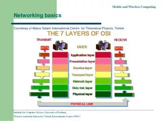
7 Application 6 Presentation 5 Session Transport 4 Network 3 2 Data Link 1 Physical OSI Model • APPLICATION • Upper Layers • Application oriented • Independent of layers below • TRANSPORT • Lower Layers • Transmission of data • No differentiation of upper layers
Layers 7, 6, 5 • 7: Application layer • Provides different services to the applications • Uses the underlying layers to carry out work • e.g. SMTP (mail), HTTP (web), Telnet, FTP, DNS • 6: Presentation layer • Converts data from applications into common format and vice versa • 5: Session layer • organizes and synchronizes the exchange of data between application processes
Layer 4 • 4: Transport layer • Provides end to end transportation of segments • E.g. TCP • encapsulates TCP segments in network layer packets • adds reliability by detecting and retransmitting lost packets • uses acknowledgements and sequence numbers to keep track of successful, out-of-order, and lost packets • timers help differentiate between loss and delay • UDP is much simpler: no reliability features
Layer 3 • 3: Network layer • Routes the information in the network • E.g. IP is a network layer implementation which defines addresses in such a way that route selection can be determined. • Single address space for the entire internetwork • adds an additional layer of addressing, e.g. IP address, which is different from MAC address.
Layer 3 • 3: Network layer (e.g. IP) • Unreliable (best effort) • if packet gets lost, network layer doesn’t care for higher layers can resend lost packets • Forwards packets hop by hop • encapsulates network layer packet inside data link layer frame • different framing on different underlying network types • receive from one link, forward to another link • There can be many hops from source to destination
Layer 3 • 3: Network layer (e.g. IP) • Makes routing decisions • how can the packet be sent closer to its destination? • forwarding and routing tables embody “knowledge” of network topology • routers can talk to each other to exchange information about network topology
Layer 2 • 2: Data Link layer • Provides reliable transit of data across a physical network link • bundles bits into frames and moves frames between hosts on the same link • a frame has a definite start, end, size • often also a definite source and destination link-layer address (e.g. Ethernet MAC address) • some link layers detect corrupted frames while other layers re-send corrupted frames (NOT Ethernet)
Layer 1 • 1: Physical layer • moves bits using voltage, light, radio, etc. • no concept of bytes or frames • bits are defined by voltage levels, or similar physical properties 1101001000
7 Application Application 6 Presentation 5 Session Transport Transport 4 Network Network 3 2 Data Link 1 Data Link & Physical Physical OSI and TCP/IP Mail, Web, etc. TCP/UDP – end to end reliability IP - Forwarding (best-effort) Framing, delivery Raw signal OSI TCP/IP
SMTP HTTP FTP Telnet DNS Audio Video TCP UDP RTP IP Token Ring Frame Relay Ethernet ATM X.25 PPP HDLC Protocol Layers:The TCP/IP Hourglass Model Application layer Transport layer Network layer Data link layer
Layer Interaction • Application, Presentation and Session protocols are end-to-end • Transport protocol is end-to-end • encapsulation/decapsulation over network protocol on end systems • Network protocol is throughout the internetwork • encapsulation/decapsulation over data link protocol at each hop • Link and physical layers may be different on each hop
Application Application Presentation Presentation Session Session Transport Transport Network Network Network Network Link Link Link Link Link Link Physical Physical Physical Layer Interaction:OSI 7-Layer Model End to end Hop by hop Router Host Host Router
Application Application TCP or UDP TCP or UDP IP IP IP IP Link Link Link Link Link Link Physical Physical Physical Layer Interaction:TCP/IP Model No session or presentation layers in TCP/IP model End to end Hop by hop Router Host Host Router
Data Header Transport Layer Data Header Network Layer Data Header Header Data Trailer Header Link Layer Data Header Header Header Data Trailer Encapsulation & Decapsulation • Lower layers add headers (and sometimes trailers) to data from higher layers Application Transport Network Network Data Link Data Link
Frame, Datagram, Segment, Packet • Different names for packets at different layers • Ethernet (link layer) frame • IP (network layer) datagram • TCP (transport layer) segment • Terminology is not strictly followed • we often just use the term “packet” at any layer
Layer 2 - Ethernet frame Preamble Dest Source Length Type Data CRC • Destination and source are 48-bit MAC addresses • Type 0x0800 means that the data portion of the Ethernet frame contains an IP datagram. Type 0x0806 for ARP. 6 bytes 6 bytes 2 bytes 2 bytes 46 to 1500 bytes 4 bytes
Layer 3 - IP datagram Version IHL Type of Service Total Length Identification Flags Fragment Offset Time to Live Protocol Header Checksum Source Address Destination Address Options Padding Data • Version = 4 • If no options, IHL = 5 • Source and Destination are 32-bit IP addresses • Protocol = 6 means data portion contains a TCP segment. Protocol = 17 means UDP.
Layer 4 - TCP segment Source Port Destination Port Sequence Number Acknowledgement Number Data Offset Reserved URG ACK EOL RST SYN FIN Window Checksum Urgent Pointer Options Padding Data Source and Destination are 16-bit TCP port numbers (IP addresses are implied by the IP header) If no options, Data Offset = 5 (which means 20 octets)
Purpose of an IP address • Unique Identification of • SourceSometimes used for security or policy-based filtering of data • DestinationSo the networks know where to send the data • Network Independent Format • IP over anything
Purpose of an IP Address • Identifies a machine’s connection to a network • Physically moving a machine from one network to another requires changing the IP address • Assigned by an appropriate authority such as RIPE, ARIN, AFRINIC, etc. or Local Internet Registries (LIRs) • TCP/IP uses unique 32-bit addresses
133 27 162 125 10000101 00011011 10100010 01111101 85 1B A2 7D Basic Structure of an IP Address • 32 bit number (4 octet number):(e.g. 133.27.162.125) • Decimal Representation: • Binary Representation: • Hexadecimal Representation:
HUB HUB PC Router PC Router HUB HUB PC PC Router Router HUB HUB PC PC Router Router HUB HUB PC PC Router Router HUB HUB PC PC Router Router Address Exercise A B C D E F G H I J SWITCH
Address Exercise • Construct an IP address for your router’s connection to the backbone network. • 196.200.220.x • x = 1 for row A, 2 for row B, etc. • Write it in decimal form as well as binary form.
Addressing in Internetworks • The problem we have • More than one physical network • Different Locations • Larger number of computers • Need structure in IP addresses • network part identifies which network in the internetwork (e.g. the Internet) • host part identifies host on that network
Address Structure Revisited • Hierarchical Division in IP Address: • Network Part (Prefix) • describes which physical network • Host Part (Host Address) • describes which host on that network • Boundary can be anywhere • very often NOT at a multiple of 8 bits 1 205 . 154 . 8 11001101 10011010 00001000 00000001 Network Host
Network Masks • Network Masks help define which bits are used to describe the Network Part and which for hosts • Different Representations: • decimal dot notation: 255.255.224.0 • binary: 11111111 11111111 11100000 00000000 • hexadecimal: 0xFFFFE000 • number of network bits: /19 • Binary AND of 32 bit IP address with 32 bit netmask yields network part of address
Example Prefixes 1000 1001 1001 1110 1 000 0000 0000 0000 1100 0110 1000 0110 0000 0000 0000 0000 1100 1101 0010 0101 1100 0001 10 00 0000 • 137.158.128.0/17 (netmask 255.255.128.0) 1111 1111 1111 1111 1 000 0000 0000 0000 • 198.134.0.0/16 (netmask 255.255.0.0) 1111 1111 1111 1111 0000 0000 0000 0000 • 205.37.193.128/26(netmask 255.255.255.192) 1111 1111 1111 1111 1111 1111 11 00 0000
Special Addresses • All 0’s in host part: Represents Network • e.g. 193.0.0.0/24 • e.g. 138.37.128.0/17 • All 1’s in host part: Broadcast • e.g. 137.156.255.255 (137.156.0.0/16) • e.g. 134.132.100.255 (134.132.100.0/24) • e.g. 190.0.127.255 (190.0.0.0/17) • 127.0.0.0/8: Loopback address (127.0.0.1) • 0.0.0.0: Various special purposes
Allocating IP Addresses • The subnet mask is used to define size of a network • E.g a subnet mask of 255.255.255.0 or /24 implies 32-24=8 host bits • 2^8 minus 2 = 254 possible hosts • Similarly a subnet mask of 255.255.255.224 or /27 implies 32-27=5 hosts bits • 2^5 minus 2 = 30 possible hosts
More Address Exercises • Assuming there are 11 routers on the classroom backbone network: • what is the minimum number of host bits needed to address each router with a unique IP address? • what is the corresponding prefix length? • what is the corresponding netmask (in decimal)? • how many hosts could be handled with that netmask?
More levels of address hierarchy • Remember hierarchical division of IP address into network part and host part • Similarly, we can group several networks into a larger block, or divide a large block into several smaller blocks • arbitrary number of levels of hierarchy • blocks don’t all need to be the same size • Old systems used more restrictive rules • New rules are “classless” • Old style used Class A, B, C networks
Old-style classes of IP addresses • Different classes used to represent different sizes of network (small, medium, large) • Class A networks (large): • 8 bits network, 24 bits host (/8, 255.0.0.0) • First byte in range 0-127 • Class B networks (medium): • 16 bits network, 16 bits host (/16 ,255.255.0.0) • First byte in range 128-191 • Class C networks (small): • 24 bits network, 8 bits host (/24, 255.255.255.0) • First byte in range 192-223
Old-style classes of IP addresses • Just look at the address to tell what class it is. • Class A: 0.0.0.0 to 127.255.255.255 • binary 0xxxxxxxxxxxxxxxxxxxxxxxxxxxxxxx • Class B: 128.0.0.0 to 191.255.255.255 • binary 10xxxxxxxxxxxxxxxxxxxxxxxxxxxxxx • Class C: 192.0.0.0 to 223.255.255.255 • binary 110xxxxxxxxxxxxxxxxxxxxxxxxxxxxx • Class D: (multicast) 224.0.0.0 to 239.255.255.255 • binary 1110xxxxxxxxxxxxxxxxxxxxxxxxxxxx • Class E: (reserved) 240.0.0.0 to 255.255.255.255
Netmasks of classful addresses • A classful network has a “natural” or “implied” prefix length or netmask: • Class A: prefix length /8 (netmask 255.0.0.0) • Class B: prefix length /16 (netmask 255.255.0.0) • Class C: prefix length /24 (netmask 255.255.255.0) • Old routing systems often used implied netmasks • Modern routing systems always use explicit prefix lengths or netmasks
Traditional subnetting of classful networks • Old routing systems allowed a classful network to be divided into subnets • All subnets (of the same classful net) had to be the same size and have the same netmask • Subnets could not be subdivided any further • None of these restrictions apply in modern systems
Traditional Supernetting • Some traditional routing systems allowed supernets to be formed by combining adjacent classful nets. • e.g. combine two Class C networks (with consecutive numbers) into a supernet with netmask 255.255.254.0 • Modern systems use more general classless mechanisms.