Optical Absorption and Absorbance in BioTek ELx800 System
420 likes | 445 Views
Explore the concepts of optical absorption and absorbance in the context of the BioTek ELx800 system. Learn about transmittance, absorbance values, optics components, gain values, photodiode usage, and system testing protocols.

Optical Absorption and Absorbance in BioTek ELx800 System
E N D
Presentation Transcript
Color Wavelength (nm) Approximate Ultraviolet 001-380 Violet 380-430 Blue 430-500 Cyan 500-520 Green 520-565 Yellow 565-590 Orange 590-625 Red 625-740 Infrared 750-1,000,000 Electromagnetic Radiation
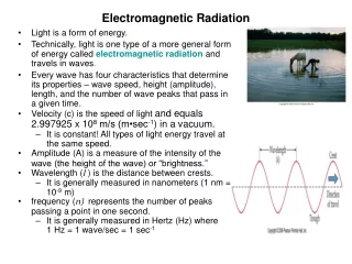
What is Optical Absorption? • Optical absorbance is the process by which the energy of a photon is taken up by another entity, for example, by an atom whose valence electrons make a transition between two electronic energy levels. The photon is destroyed in the process.
What is transmittance? It’s a fraction. It’s a fraction of light intensity ( I ).
What is Absorbance (AU)? It’s the 2 - Log10 (%Transmittance of light) 100% = 0.000 AU 50,000 counts = 0 AU 10% = 1.000 AU 5,000 counts = 1 AU 1% = 2.000 AU 500 counts = 2 AU 0.1% = 3.000 AU 50 counts = 3 AU 0.01% = 4.000 AU 5 counts = 4 AU
What is Optical Absorption? • Absorptionrefers to the physical process of absorbing light. • Absorbance refers to the mathematical quantity. We deal with absorbance reading all the time here at BioTek. • The absorbance of an object is a way to describe how much light is absorbed by the object. Another way to put it is, the absorbance of an object is a way to quantify the amount of light retained.
O.D. or Optical Density is the absorbance per unit length (in centimeters). OD λ = Absorbance λ / Length
ELx800 and newer • ELx800 readers display AD counts in the system test results • White light used (no filter) with self test • Each filter is tested
ELx800 vs. ELx808 • ELx800 and ELx808 target AD counts = 50,000 • ELx800 is effected by the meniscus of the sample being read • Due to the filter position in reference to the samples, meniscus > 100 µl with a delaminimumating (light passing by the outer edges) filter will increase the OD readings, < 100 µl has no effect unless the entire filter is bad. • ELx800 has the filter after the sample • ELx808 has the filter before the sample (better design)
ELx800 Optics System Mirror Lamp Focusing Lens Microplate Filter Filter Focusing Lens IR Lens DATA Filter wheel motor Photodiode
300ul 300ul 250ul 250ul 200ul 200ul 150ul 150ul 100ul 100ul 50ul 50ul ELx800 Optics System (Continued) • Microplate (Flat Bottom) • Fluid used is DI water from 50 µl to 300 µl • Approx 0.048 – 0.056 OD OK • Above 0.100 OD not OK • CV should not vary more than 0.020 across the plate
ELx808 Optics System Fiber optic spray IR Lens Focusing Lens Focusing Lens Reference channel Lamp Microplate Filter wheel motor Filters Photodiodes DATA
System Test (Filter units ELx800 and ELx808) • 380 nm – 800 nm • Gain values 1.4 – 36.56 • 340 nm • Gain values 1.4 – 36.56, 52.58, 64, 128 • Very little light at 340 nm. The system is able to step up the gain higher than non UV filters • The downside is that the resolution is not as good with the gain adjustments.
How does the reader use the photodiode to measure OD? • Takes an ambient light reading. • Takes a full light reading • Calculates the difference, equals 100% of the available signal • Reads a sample and calculates the fraction (%) of full light transmitted through the well • Calculates 2-Log10 of % (calculates OD value) • Outputs Data
System Test (Filter units ELx800 and ELx808) (Continued) Why is the 1.4 gain value so important? • When the system test starts, the gain is at 1 • The target of 50,000 counts must not be reached at a gain of 1 • All channels are checked for 50,000 counts • The target of 50,000 counts must not be reached below a gain of 1.4 to ensure the system has an adjustable range • An error will occur if 50,000 counts is reached before the gain is < 1.4
System Test (Filter units ELx800 and ELx808) (Continued) • Dark Current • Electrical noise of the entire instrument with the same gain applied • as the air readings. • Typical readings 3000 – 5000: Errors at >10000 and <100 • Air Readings • White light reading. Gain is applied until one channel reaches 50,000 counts. • Reference channel should never reach 50,000. • Typical readings 46,000 – system can go up to 65,556 • A reading of 65,556 should never be reached.
System Test (Filter units ELx800 and ELx808) (Continued) • Noise test • Electrical noise of entire system with maximum gain applied. The • minimum and maximum readings measure the ripple. • The delta is the peak to peak of the ripple • The delta must be less then 20 counts • Errors if readings are <100 and >10,000 Note: If the noise test fails, possible causes are: • A bad ground: analog PCB has a bad connection with ribbon cable. • Some electrical device inside of unit making excessive noise: one of the channels has gone bad
System Test (Filter units ELx800 and ELx808) (Continued) • The noise test is performed first, then the Air values determined to get gain settings. The Dark readings are taken last at the determined gain setting. • There is a plug with a pin hole on the upper lens block on the ELx808 readers to reduce the amount of light exposed to the reference channel. The Delta between the Air and Dark readings must be grater than 20,000 counts. • A good check for ELx808 reader is: • The Dark readings are proportional to the gain • If a test at 405 nm has a gain of 8 and a Dark reading of 1000 then if 590 nm has a gain of 4 the Dark current should be around 500 • The ELx800 dark current is set to 1000 – 1200 for all gains. • The reference channel values are half of the channels
System Test (Filter units ELx800 and ELx808) (Continued) • The self test data is stored on board. If the user changes a 405 nm filter with another 405 nm filter and performs a read, there is a good chance the reader will error indicating the air value has changed since the last read. A self test will clear this condition by storing the new value. • The self test is performed before and after the read.
System Test (Filter units ELx800 and ELx808) (Continued) • This is an example of an • ELx800 self test. • This example only shows 4 filters to allow larger print.
System Test (Filter units ELx800 and ELx808) (Continued) • This is an example of an ELx808 self test.
Flash Technology - Monochromator • BioTek’s spectrophotometer absorbance readers use flash technology. • Flash technology in BioTek readers use a Xenon flash lamp and a monochromator. • What is a monochromator? • A monochromator is a device that has a rotating mirror with • gradients to split up the light spectrum. • BioTek’s monochromator wavelength spectrum is from 200 to 999 • nm
Flash Technology – Finding home • The system home’s the monochromator • by turning the mirror clockwise until the white light completely passes the output slit. A no light condition is met. • The mirror will then move counterclockwise until the white light starts to pass through the output slit. A no light to maximum light condition is met. This is considered home. If it does not find home, Error 303 Dark Home Spectrum Lamp
Dark Home Spectrum Lamp Flash Technology – Finding home • Error 403 – Monochromator stepper • motor step accuracy test. • The motor steps a number of counts in • one direction and moves back the same • number of steps, in the reverse direction. • While moving back, the system is • monitoring the white light condition. Once it found the white light, the • steps counter should be zero, ± some error band. • This error can be caused by: • An intermittent flash lamp • Op amp rail. • If the system is looking for the light to no light condition to find home and the lamp fails to flash, the system thinks it is at home, but actually it is not.
Flashing Technology • The theory behind the flashing technology is the ability to store light energy until a predetermined level is achieved. Remove the energy and start all over again. • Resets are used to coarse adjust to Quantify (determine the amount) the of light energy • Gain is used to fine adjust the light energy. Keeping the gain low keeps the noise low. • The Ratio, Resets/Gain, is used as a measure of light energy. • Flashes – Normal mode 8 flashes are used up to 2 OD 64 flashes are used above 2 OD • – Rapid mode 8 flashes up to 4 OD • – Sweep mode only uses 1 flash
Flashing Technology: Optics Functionality C1 R1 R3 R2 40,000 40,000 • - Gain = 1 • - Open R2 • - R1 closes when flashing, open R1 to store • - After flash, R3 closes to read. • - If 40,000 counts is not met R3 opens, R1 closes • The above loop continues until 40,000 counts is met • The Gain is adjusted to achieve the 40,000 counts • - R2 closes to drain the stored energy in C1 (Reset) • -The cycle starts all over again. • If 40,000 counts is met after 2 flashes • R1 and R3 opens • R2 closes to reset • This loop will continue four more times for a total of 4 resets • within 8 flashes • Resets can be 1, 2, 4, 8 with in 8 flashes.
Flash Technology: System Test • This is an example of a PowerWaveX self test. • This example only shows 4 filters to allow larger print.
Flashing Technology: System Test • Which has more energy? • Gain = 3 Reset 1 • Gain = 3 Reset 4 • *Gain = 3 Reset 4 has more energy* • Ratio of energy = Reset/Gain
Flashing Technology: Gain Test • Used to test and calibrate entire light path from 200 to 999 nm. • Data points are based on the ratio of energy = (8 resets / 1.4 gain) if less then • 1.4 then air reading should not exceed 50,000 counts. • A quick check is the reading around 640nm should not be less than 0.25 • The exception is the PowerWave HT (fiber optics and channels are smaller). • For all Monochromator readers the reading at 639 must not be less then 0.1
Flashing Technology: Gain Test (Continued) • When calibrating a lambda and the circuit determines that 4 flashes are needed (2 resets) then, when the reader is reading a plate, only 4 flashes will be used. • This saves time and prolongs the bulb. Resets not used. • The gain test is stored onboard to speed up the read time. Should a lambda of 430nm be chosen, the software will look at the gain test and start with the settings recorded. This also saves time.
Flashing Technology: Gain Test (Continued) • On single channel readers a gain of 1 resets of 8 can be reached. The new Excel sheets will display the air readings. The user must determine if the air readings are acceptable.
Flashing Technology: Wavelength vs. Voltage µQuant / Single channelInitialization use 3.48V Homing - 3.48v 200 – 224 use 6.0V225 - 244 use 3.48V245 – 309 use 4.25V 310 - 409 use 6.0V 410 - 559 use 5.25V560 - 999 use 6.0V 1V = 100V to flash lamp 6V = 600V to flash lamp
Flashing Technology: Wavelength vs. Voltage PRWX / Multi channelHoming – 3.48v 200 – 224 use 8.0V225 – 244 use 3.5V245 – 309 use 5.0V310 – 409 use 8.0V 410 – 559 use 6.5V 560 – 999 use 8.0V 1V = 100V to flash lamp 8V = 800V to flash lamp
Flashing Technology: Order Sorting Filters • Used to prevent light harmonics from entering the monochromator. They • are not filters. • 5 filters – See assembly drawing below. • Filter #1 UG5 will brake down due to UV bombardment.
Flashing Technology: Filter number / Frequency cutoff • Filter number / Frequency cutoff • No filter / 200 – 241 nm • #1 / 242 – 369 nm • #2 / 370 – 459 nm • #3 / 460 – 569 nm • #4 / 570 – 634 nm • #5 / 635 – 999 nm • The Filter test only goes to 800nm
Flashing Technology: Defective Filter • What's wrong with the center graph? • A) Voltage getting to the flash lamp? • B) Filter #1 UG5 filter gone bad? • C) Bad alignment? • Answer Filter #1 UG5 filter gone bad from UV bombardment
Flashing Technology: Poor Light Energy • What's wrong with the 2nd graph? • A) Voltage getting to the flash lamp? • B) All Filters gone bad? • C) Bad alignment? • AnswerBottom graph shows not enough light dueto bad alignment.
Flashing Technology: Poor Light Energy • What's wrong with the bottom graph? • A) Voltage getting to the flash lamp? • B) All Filters gone bad? • C) Bad alignment? • Answer Bad alignment. Bottom graph shows not enough light.