Download
1 / 17
170 likes | 184 Views
Testing Network Protocols with Timers. M. Ü mit Uyar, Yu Wang, Samrat S. Batth The City College of the City University of New York Adriana Wise Graduate Center of the City University of New York Mariusz A. Fecko Telcordia Technologies Inc. NYMAN 2004

E N D
Testing Network Protocols with Timers M. Ümit Uyar, Yu Wang, Samrat S. Batth The City College of the City University of New York Adriana Wise Graduate Center of the City University of New York Mariusz A. Fecko Telcordia Technologies Inc. NYMAN 2004 September 10, 2004, Graduate Center ,CUNY
Outline • IUT represented by FSM and a set of timers K={tm1, … , tmk}, which can be started and stopped by arbitrary transitions • Problems: faults due to non-conformance to time constraints • 1-Clock Timing Constraints: 1-clock interval constraints • n-Clock Timing Constraints: events happening in a given orde • Timer Settings Constraints: incorrect settings of timer lengths either too short or too long • Solutions sought: detect various timing faults by augmenting the FSM model of the specification
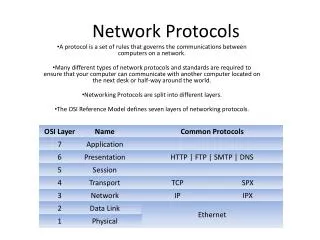
v0 v2 v1 <T2==1∧f2≥D2>{T2:= 0; f2:=-∞} <T1==1∧T2==1> {T1:= T1; f1:= f1 + c4 ; T2:= T2; f2:= f2 + c4} e9 <T1==1∧T2==1> {T1:= T1; f1:= f1 + c4 ; T2:= T2; f2:= f2 + c4} T2 timeoutedge e5 e3 v3 <T1==1∧T2==1> {T1:= T1; f1:= f1 + c4 ; T2:= T2; f2:= f2 + c4} e4 <T1==1∧f1≥D1 ∧T2==1∧f2<D2> {T1:= 0; f1:=-∞; T2:=T2; f2:= f2+c6} <T1==0∧T2==1∧f2 [5, 9]> {T2:=0; f2:=-∞} <T1==1∧T2==1> {T1:= T1; f1:=f1+c2; T2:=T2; f2:= f2+c2} stop T2 e7 e1 start T1,T2 T1 timeoutedge e6 e2 both timers running e8 stop T1 <T1==1∧T2==1> {T1:=0; f1:=-∞ T2:=T2; f2:= f2+c2} Example Specification for a Timed FSM • timers tm1 and tm2 are started by the action of the edge e1. • each edge’s cost is 1 time unit except edges e3 and e5, which are c3 = 2, c5 = 2 • timer lengths D1=5 time units and D2= 9 time units. • The conditions for e6 and e9 are the timeout edges for tm1 and tm2, respectively. • e8 may stop timer tm1 and e7 may stop timer tm2. • edge conditions and actions are indicated in the graph. • The test sequence generated is e1e8e7 e1e2e3e4e5e6e7 e1e2e3e4e9 Example specification for a Timed FSM
Novel Model for Systems with Timers [IEEE ToN 2003] • Complex timing dependencies in FSM are captured by using simple linear expressions with the following parameters: • Tj—boolean variable indicating if timer tmj is running • Dj—the timeout value (i.e., the time length of tmj) • fj—time-keeping variable for the current time of tmj • Following are defined for transition ei =(vp,vq,ai,oi,<>,{i,1,…}): • allowed input ai/- at current state vp • observed output oi/- from current transition • traversal time ci from current state vp to the next state vq • time condition <>,e.g., <>= <T1 ==1 T2 ==0> • action list {i,1,i,2, …}, e.g., {T1:=1; f1:= f1+5; T2:=0; f2:= -∞} • timers that are started or stopped in ei e.g., tm2stopped {T2:=0; f2:= -∞}
Benefits of the new model (1) • model tailor-designed for testing purposes • no full reachability analysis • more intuitive modeling of an IUT and testing procedure • each I/O exchange assigned time to realize • no instantaneous transitions as in TA • timers remain in either on or off state • allows to define a timer length as a constant or variable rather than a fixed value as in TA • modeling of service delivery, proper timeout settings, etc.
Benefits of the new model (2) • does not require trial-and-error sampling of time state space • it advances time based on transition execution values defined in the specification • uses a paradigm of Extended Finite State Machines • easily applicable to languages such as Estelle, VHDL, and SDL • enables testing timed systems with numerous EFSM- and FSM-based test generation methodologies reported in the literature • rules for the graph traversal • significantly limit the explosive growth of the number test cases • no reduction of the set of testable transitions
Benefits and Drawback of Our Timed FSM Augmentation • Our graph augmentation is introduced into the FSM model • a set of special purpose timers • corresponding waiting states with their respective edges • state and edge splitting • Benefits of augmenting the FSM model • Test sequences generated from augmented model force faulty implementations to traverse pre-determined transitions • All single timing faults can be detected • Drawback of augmenting the FSM model • FSM becomes Extended FSM (EFSM) • Test sequences generation is more difficult than FSM models • Must use EFSM test generation techniques (e.g., by Duale and Uyar [1])
oi ai ci<θ Input interval ck α δ+ci δ+θ δ β β+θ α +θ 0 time Timing Fault Type: 1- Clock Timing Faults • Timing Requirement:hk is a transition prior to ei. Transition ei =(vp,vq,ai,oi) can correctly trigger only after applying input ai within required time intervals δ[α,β], measured from the execution of transition hk. • Timing fault I: Input ai is not applied within the required time intervals, either too early δ'<α or too late δ">β , output oi may be observed and state vq verified in no later than θ time after applying ai • Timing fault II: Input ai is applied within the required time intervals δ[α,β], output is not observed ¬oior state vq can not be verified in less than δ+θ time Timeline Representation of Interval Requirement
vq vk vk+1 vk vq vk+1 Detection of 1- Clock Timing Faults <(T1==0)∧(T2==1)∧(f2[α,β])> {T1:= 0; f1:= -∞; T2:=0; f2:=-∞} <(f1<α)∧(f2<β)> {T1:=1; f1:=0; T2:=1; f2:=0} ai vp ei(vp,vq,ai,oi,…) hk Specification for FSM Graph w1 w2 <(T1==1)∧(f1<α)∧(T2==1)∧(f2<α )> {T1:=T1; f1:=f1+cw1 ; T2:=T2; f2:=f2+cw1} < (T1==0) ∧(T2==1)∧(f2<β)> {T1:=0; f1:=-∞; T2:=T2; f2:=f2+cw2} ew2 ew1 er1 er2 < (T1==1)∧(f1 ≥ α) ∧T2==1)∧(f2 <β) > {T1:=0; f1:=-∞; T2:= T2; f2:= f2;} {} {} <(f1<α)∧(f2<β)> {T1:=1; f1:=0; T2:=1; f2:=0} <(T1==0)∧(T2==1)∧(f2[α,β])> {T1:= 0; f1:=-∞; T2:=0; f2:=-∞} ai v2p v1p ep ei(vp,vq,ai,oi,…) hk ai ai ai ei (…ai, ¬oi,…) ei'(…, ai,oi'…) ei"(…ai,oi"…) <(T1==0)∧(T2==1)∧(f2[α,β])> {T1:= 0; f1:=-∞1; T2:=0; f2:=-∞} <(T2==1)∧(f2>β)> {T2:=0; f2:=-∞} <(T1==1)∧(f1<α)∧(T2==1)∧(f2<β)> {T1:=T1; f1:=f1+ci´;T2:=T2; f2:=f2+ ci´} vq2 fault II vq1' fault I vq1" fault I Augmented Graph for Fault I and Fault II Coverage
< Tk-1==1 ∧ fk-1 < Dk-1 > {Tk:=1; fk:=0} < Tk==1∧ fk< Dk > {Tk+1:=1; fk+1:=0} < Tn-1==1 ∧ fn-1 < Dn-1 > {Tn:=1; fn:=0} {T1:=1; f1:=0} < Tn==1 > hk+1 hn hk vp vq vk vk+1 vk+2 vn v1 ei h1 Timing Fault Type: n- Clock Timing Faults • TimingRequirement: The transition ei =(vp,vq,ai,oi,<t>,{t}) following a suite of transitions ρ=h1· · · hk hk+1 · · ·hn , can trigger after applying input ai only when, for ∀k [1, n),hk was executed before hk+1 • Timing Fault III: The order of the preceding transitions was not respected and the relation between transitions didn’t hold, i.e., h1· · · hk+1 hk · · ·hn. For at least one ∃k [1, n),hk+1was executed before hk, as a result of which the tail state of a suite of transitions h1· · · hk+1 hk · · ·hn hn+1v'q≠vq is verified and the tail output o'i ≠oi is observed in less than θ time, measured from the time of applying input ai Specification for FSM Graph
h1k vk+1 vk vk+1 vk hk h2k fault III < Tn-1==1∧fn-1<Dn-1 > {Tn:=1; fn:=0} < Tk-1==1∧fk-1<Dk-1 > {Tk:=1; fk:=0} < Tk==1∧fk< Dk> {Tk+1:=1; fk+1:=0} {T1:=1; f1:=0} h1k+1 h1n h1k < Tn==1> vp vq vk vk+1 vk+2 vn v1 ei h1 <Tk-1==0> {Tk:= 0} <Tk==0> {Tk+1:=0} < Tn-1==0 > {Tn:=0} <Tn ==0> {} ei' h2k+1 h2k h2n fault III fault III fault III fault III fault III Detection of n- Clock Timing Faults • Traversal sequence becomes feasible h1· · · h1k h1k+1 · · ·h1n ei only if all the respective edge conditions for special timers are met • Traversal sequence becomes infeasible h1· · · h1k+1 h1k · · ·h1n ei since the condition of transition h1k+1:< Tk==1∧fk< Dk> could not be satisfied, tmkonly can be started in the transition h1k. Instead, h1· · · h2k+1traverses by attaining state fault III Augmented Graph for Fault I and Fault II Coverage
oi – ci<θ vn cn ck 0 time Dj Dj+ ci Timing Fault Type: Incorrect Timer Setting • Timing Requirement: Dj is the length of timer tmj. Timeout transition ei =(vp,vq,-,oi,<t>,{t}) will trigger exactly in Dj time unit after tmj was started in previous transition hk • Timing Fault IV: Timeout transition ei =(vp,vq,-,oi,<t>,{t}) will trigger in D'j< Dj time, measured from the execution of previous transition hk. Output oi may be observed and state vq verified in less than time Dj + ci • Timing Fault V: Timeout transition ei =(vp,vq,-,oi,<t>,{t}) will trigger in D'j> Dj time, measured from the execution of previous transition hk. Output oi may be observed and state vq verified in more than time Dj + ci
vk vn+2 vn-1 <Tj ==1∧fj ≥Dj> Tj Timeout <Tj==0> {Tj:=1; fj:=0} <(Tj==1)∧(Dj –fj ≤cn)> Tj non-Timeout <(Tj==1)∧(Dj –fj>ck+1)> Tj non-Timeout vn+2 vk+2 vq vk+1 vp vn hk ei hn hn+1 w1 w2 ew2 ew1 <(Tj==1)∧(fj<Dj)∧(Dj –fj<cn)> {Tj:=Tj; fj:=fj+cw1} < (Tj==1)∧(fj<Dj)∧(Dj –fj<cn)> {Tj:=Tj; fj:=fj+cw2} er1 er2 {} {} <(Tj ==1)∧(fj>Dj)> Tj non-Timeout <Tj==0> {Tj:=1; fj:=0} <Tj ==1∧fj ==Dj -ε> Tj non-Timeout <Tj ==1∧fj ==Dj> Tj non-Timeout <(Tj==1)∧(Dj –fj>cn-1)> Tj non-Timeout v1n vk+1 vk v2n vn+1 fault IV fault V hk en hn-1 hn hn+1 h2n <(Tj ==1)∧(fj>Dj)> Tj Timeout <(Tj ==1)∧(fj>Dj)> Tj Timeout <(Tj==1)∧(Dj –fj>cn-1)> Tj Timeout <(Tj==1)∧(fj<Dj)∧(Dj –fj<cn)> Tj Timeout <Tj==1∧fj ==Dj> Tj Timeout correct setting conform fault IV fault V Detection of Incorrect Timer Setting Faults Specification for FSM Graph Augmented Graph for Fault I and Fault II Coverage
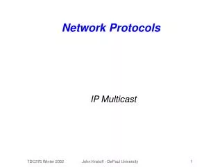
v0 v1 v3 Augmented Graph of the Timed FSM example <T2==1∧f2≥D2>{T2:= 0; f2:=-∞} • The test sequence generated in EFSM is e1e8e7 e1e2e3e4e5e6e7 e1e2e3e4ew1er1 ew2er2e9 • Fault I and II can be detected • Require applying input ai at edge e7: <f2 [5, 9]>. Traversal follows e1e2e3e4e5e6e7 sequence. e5 :{f1:=6; f2:=6}, e6 :{f1:=-∞; f2:=7}. If applying ai too early or too late, other edge triggers. • Fault III can be detected • Expected traversal sequence is e1e2e3e4. e3:<T1==1∧T2==1>can not be traversal before the edge e1 :<T1:=1∧T2:=1>. If this order doesn’t hold, the test sequence will stop and error will be caught, i.e, e3e2e1e4 <T1==1∧T2==1> {T1:= T1; f1:= f1 + c4 ; T2:= T2; f2:= f2 + c4} <T1==1∧T2==1> {T1:= T1; f1:= f1 + c4 ; T2:= T2; f2:= f2 + c4} e9 T2 timeoutedge fault IV e3 e5 <T1==1∧T2==1> {T1:= T1; f1:= f1 + c4 ; T2:= T2; f2:= f2 + c4} ew1 e4 wait1 v2 er1 ew2 er2 fault III wait2 <T1==0∧T2==1 ∧f2 [5, 9]> {T2:=0; f2:=-∞} fault V <T1==1∧T2==1> {T1:= T1; f1:=f1+c2; T2:=T2; f2:= f2+c2} stop T2 e7 <T1==1∧f1≥D1 ∧T2==1∧f2<D2> {T1:= 0; f1:=-∞; T2:=T2; f2:= f2+c6} e1 start T1,T2 e2 both timers running e6 T1 timeoutedge e8 stop T1 <T1==1∧T2==1> {T1:=0; f1:=-∞ T2:=T2; f2:= f2+c2} D1=5.0, D2= 9.0; c3 = 2, c5 = 2, other edge’s cost is 1 Augmented Graph of Example Specification for a Given Timed FSM
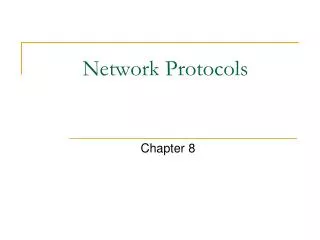
v0 v1 v3 Augmented Graph of the Timed FSM example <T2==1∧f2≥D2>{T2:= 0; f2:=-∞} • The test sequence generated is e1e8e7 e1e2e3e4e5e6e7 e1e2e3e4ew1er1 ew2er2e9 • Fault IV and Fault IV can be detected • Assume we concern the timer tm2 setting too short or too long • Two wait state are introduced into the original graph. Traversal sequence follows e1e2e3e4ew1er1 ew2er2e9 • e4 :{f1:=3; f2:=3} • The wait state wait1with wait edge cost cw1= D2 -f2 –є andtimeout transition follows. Fault IV can be detected • The wait state wait2with wait edge cost cw2= D2 -f2 and timeout transition not follows.Fault V can be detected <T1==1∧T2==1> {T1:= T1; f1:= f1 + c4 ; T2:= T2; f2:= f2 + c4} <T1==1∧T2==1> {T1:= T1; f1:= f1 + c4 ; T2:= T2; f2:= f2 + c4} e9 T2 timeoutedge fault IV e3 e5 <T1==1∧T2==1> {T1:= T1; f1:= f1 + c4 ; T2:= T2; f2:= f2 + c4} ew1 e4 wait1 v2 er1 ew2 er2 fault III wait2 <T1==0∧T2==1 ∧f2 [5, 9]> {T2:=0; f2:=-∞} fault V <T1==1∧T2==1> {T1:= T1; f1:=f1+c2; T2:=T2; f2:= f2+c2} stop T2 e7 <T1==1∧f1≥D1 ∧T2==1∧f2<D2> {T1:= 0; f1:=-∞; T2:=T2; f2:= f2+c6} e1 start T1,T2 e2 both timers running e6 T1 timeoutedge e8 stop T1 <T1==1∧T2==1> {T1:=0; f1:=-∞ T2:=T2; f2:= f2+c2} D1=5.0, D2= 9.0; c3 = 2, c5 = 2, other edge’s cost is 1 Augmented Graph of Example Specification for a Given Timed FSM
Summary • Powerful FSM Model for Network Systems with Timers • Directly applicable to test sequence generation • Can detect the following timing faults: • 1- Clock Timing Faults • n- Clock Timing Faults • Incorrect Timer Setting Faults • After augmentation, we obtain EFSM (FSM with variables) from which we can generate test sequences directly (see the technique by Uyar and Duale [1]) • Will apply this technique to multiple timing faults as future work
References • [1] A. Y. Duale and M. U. Uyar. A Method Enabling Feasible Conformance Test Sequence Generation for EFSM Models. IEEE Transactions on Computers, Volume 53, No. 5, pp. 614-627, May 2004. • [2] A. Fecko, M. U. Uyar, A. Y. Duale, P. D. Amer, A Technique to Generate Feasible Tests for Communications Systems with Multiple Timers, IEEE/ACM Transactions on Networking, V. 11, No. 5, pp. 796-809, Oct. 2003. • [3] M. U. Uyar, M. A. Fecko, A. Y. Duale, P. D. Amer, A. S. Sethi, ”Experience in Developing Network Protocol Software Using FDTs, (invited paper) Journal of Information and Software Technology, Elsevier Science B. V., No 45, Issue 12, pp. 815-823, September, 2003.