Download
1 / 16
170 likes | 392 Views
MSN 510 Imaging Techniques in Materials Science and Nanotechnology. Instructor: Aykutlu Dana UNAM Institute of Materials Science and Nanotechnology, Bilkent, Ankara-Turkey. Course Organization. Class outline Homeworks Extensive Matlab Simulations Laboratory Work Preparations Laboratory

E N D
MSN 510Imaging Techniques in Materials Science and Nanotechnology Instructor: Aykutlu Dana UNAM Institute of Materials Science and Nanotechnology, Bilkent, Ankara-Turkey
Course Organization • Class outline • Homeworks • Extensive Matlab Simulations • Laboratory Work • Preparations • Laboratory • Laboratory Report • Groups of 4 People
Why is microscopy important ? • The International Technology Roadmap for Semiconductors • Scanning probe microscopes • Giant magnetoresistive effect • Semiconductor lasers and light-emitting diodes • National Nanotechnology Initiative • Carbon fiber reinforced plastics • Materials for Li ion batteries • Carbon nanotubes • Soft lithography • Metamaterials
Why is microscopy important ? The other nine advancements heavily rely on microscopy Or are enabled by microscopy and related techniques • The International Technology Roadmap for Semiconductors • Scanning probe microscopes • Giant magnetoresistive effect • Semiconductor lasers and light-emitting diodes • National Nanotechnology Initiative • Carbon fiber reinforced plastics • Materials for Li ion batteries • Carbon nanotubes • Soft lithography • Metamaterials
Why is microscopy so important ? The other nine advancements heavily rely on microscopy Or are enabled by microscopy and related techniques Example: Carbon Nanotubes (Iijima, 1991)
Nobel Prizes • 1903 – Richard Zsigmondy develops the ultramicroscope and is able to study objects below the wavelength of light.The Nobel Prize in Chemistry 1925 • 1932 – Frits Zernike invents the phase-contrast microscope that allows the study of colorless and transparent biological materials.The Nobel Prize in Physics 1953 • 1938 – Ernst Ruska develops the electron microscope. The ability to use electrons in microscopy greatly improves the resolution and greatly expands the borders of exploration.The Nobel Prize in Physics 1986 • 1981 – Gerd Binnig and Heinrich Rohrer invent the scanning tunneling microscope that gives three-dimensional images of objects down to the atomic level.The Nobel Prize in Physics 1986 To get a feeling: http://nobelprize.org/educational_games/physics/microscopes/1.html
What is an Image? • Sample has a property distribution M(x,y,z) • An image is a map of M(x,y,z) , or a 2D cross-sectional map of M(x,y,z) • A microscope is an instrument that generates a data map from the small spatial scale property distribution M(x,y,z). • Resolution is a measure of dx, dy or dz of the generated map for distinct points providing complementary information (nonredundant)
What is an Image? • Sample has a property distribution M(x,y,z) • The property distribution may be related to • Density • Atomic number • Optical refractive index variation • Luminescent properties • Phonon density or energy • ..... etc. • We can image some specific property using an appropriately chosen probe by measuring the interaction of the probe with the sample at different x,y and z locations. • The dominant interaction of the probe with the specific property will be instrumental in imaging that property.
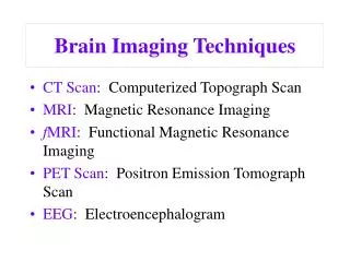
Example: Optical Light Microscope • Probe: Light of certain spectral distribution • Property to be imaged: • Optical absorption of the sample • Optical phase shifts due to refractive index variations of the sample • Luminescence properties of the sample
Parallel vs. Sequential Imaging • In parallel imaging, generally the sample or the probe is not scanned • The whole sample area to be imaged is illuminated by the probing wave in a uniform way. • Scattering, absorption or other perturbations of the wave take place at the sample. • Probe signal, now carrying information about the sample, propagates through the optical system which reconstructs the image at the detector plane. • Since image formation is done by fundamental physics laws governing propagation of the probe wave, for each point of the sample simultaneously, we refer to this imaging method as parallel imaging.
Parallel vs. Sequential Imaging • In sequential imaging, the sample or the probe is scanned • The probe has small diameter and interacts locally with the sample. • Interaction of the sample with the probe is recorded as a function of x,y or z. • Image formation is done by recording the probe signal bysecondary means(computers etc.).
Parallel Imaging uses waves • Acustic, Electromagnetic (Light), Electron waves • Wave equation (EM) • Helmholtz Equation • Harmonic waves: Separate in time and space The paraxial approximation further simplifies math.
Huygen’s Principle (Approximation) • Each point on a wavefront acts as a point source
Near Field and Far field • Near field: Right at the source • Far field (Fraunhofer): At infinity (many wavelengths away from the source) propagation We detect energy of the EM wave square Sınc squared (Fourier transform?)
Near Field and Far field • Huygens' principle when applied to an aperture simply says that the far-field diffraction pattern is the spatial Fourier transform of the aperture shape, and this is a direct by-product of using the parallel-rays approximation, which is identical to doing a plane wave decomposition of the aperture plane fields propagation Sinc [=(Sin x)/x] squared square