a ridge
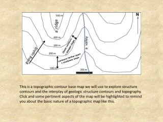
a ridge. a valley. closer contours = steeper slope. g oing uphill. contours farther apart = shallower slope.

a ridge
E N D
Presentation Transcript
a ridge a valley closer contours = steeper slope going uphill contours farther apart = shallower slope This is a topographic contour base map we will use to explore structure contours and the interplay of geologic structure contours and topography. Click and some pertinent aspects of the map will be highlighted to remind you about the basic nature of a topographic map like this.
The angle between N and the strike contour line is the strike angle (about 60 or N60E/S60W degrees here). S60W The fact that all the constructed lines are parallel and evenly spaced indicates the contact is planar. If the lines 400 m 300 m 200 m = 100 m for spacing between strike contours Imagine that the red line represents a geologic contact of some sort. Given that it doesn’t parallel contours we know it isn’t horizontal, and given that it doesn’t cut straight across contours we know it isn’t vertical. Can we tell something about its orientation? Note how we can find three points (red stars) where the geologic contact is at 200 m elevation by finding where the contact crosses the 200 m contour interval. A line through those points represents points on the contact at the same elevation, which is a strike line, specifically the 200 m strike contour line. In a similar fashion we can construct additional structure contours at other elevations for the geologic contact. Finally, using the map scale, the distance between the structure contours is about 100 m as measured perpendicular to the strike contour lines (otherwise you are working with apparent dip). That distance lets you to calculate the plane’s slope, i.e. dip angle. The dip angle is the arctan of the elevation difference divided by the strike contour spacing ( here arctan(100m/100m)=45 degrees). Thus the strike and dip of the planar contact can be obtained from its map expression. It has a 60 degree strike and 45 SW dip.
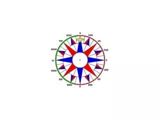
200 m 100 m 300 m 400 m You can also start with the orientation, the strike and dip of a contact, and then map out what the map pattern should look like. Imagine the contact is located at the red star and strikes 120 and dips 45 to SW. First draw the strike line that passes through the red star, which is on the 100 m topographic contour (and which therefore has to be the 100 m structure contour line. The line needs to be at the appropriate strike angle from north. We are using the strike azimuth system so the line is at a 120 clockwise angle from North. Then draw other parallel contour strike lines at the appropriate spacing and label them as to their elevation. Since this contact dips 45 degrees, that same amount it dipped in the previous example (the strike is different), the spacing is the same as in that example (chosen for convenience). Finally, find the points where the the topographic and strike contours of the same value intersect and mark them (here with the red stars), and then draw the line connecting the stars and you have the expected map expression of the planar contact with the orientation 120 – 45SW
topographic profile projection of 200 m strike contour on surface up 100 m scale bar 500 m horizontal strike contour spacing = 60 m 400 m map distance 300 m dip angle elevation difference 200 m 100 m This slide focuses on being able to compute the dip from strike contour spacing or compute the spacing from dip value. We start out with a cross section perspective along a direction perpendicular to the layer strike (so that we see the true dip), and with equal vertical and horizontal scales and a topographic profile. Blue lines show constant elevation, and the red line is the cross section view of the plane of interest that is coming in and out of the board, with the dip angle shown. From where the geologic feature crosses the elevation contours we can identify strike contour points s at different levels, representing horizontal strike contour lines that come in and out of the vertical plane. Then we can vertically project their position (dashed lines) upwards to identify the map spacing between the strike contours. You can then use the horizontal map scale to figure out what the spacing is – 60 m in this case. Finally, using the relationship that tan (dip angle) = elevation difference / map distance either the dip or the strike contour spacing can be solved for. In this case it is 59 degrees.