Download
1 / 3
30 likes | 43 Views
Canopus Instruments provides multi channel temperature scanners designed to interface with 8 / 12 / 16 channels of 3-Wire RTD PT-100 inputs as per the user requirement. http://www.canopusinstruments.com/product/industrial-automation-product/resistance-temperature-detector-scanner/rtd-temperature-scanner-canscan-1-0-7-segment-led/?utm_source=google&utm_medium=pdf&utm_content=submission

E N D
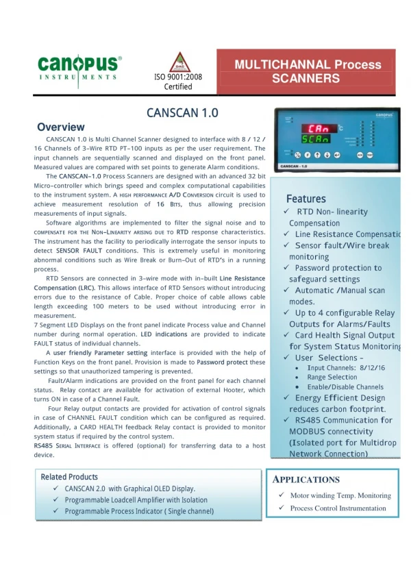
MULTICHANNAL Process SCANNERS ISO 9001:2008 Certified CANSCAN 1.0 Overview CANSCAN 1.0 is Multi Channel Scanner designed to interface with 8 / 12 / 16 Channels of 3- Wire RTD PT- 100 inputs as per the user requirement. The input channels are sequentially scanned and displayed on the front panel. Measured values are compared with set points to generate Alarm conditions. The CANSCAN- 1.0 Process Scanners are designed with an advanced 32 bit Micro- controller which brings speed and complex computational capabilities to the instrument system. A HIGH PERFORMANCE A/DCONVERSION circuit is used to achieve measurement resolution of 16BITS, thus allowing precision measurements of input signals. Software algorithms are implemented to filter the signal noise and to COMPENSATE FOR THE NON- LINEARITY ARISING DUE TO RTDresponse characteristics. The instrument has the facility to periodically interrogate the sensor inputs to detect SENSOR FAULT conditions. This is extremely useful in monitoring abnormal conditions such as Wire Break or Burn- Out of RTD’s in a running process. RTD Sensors are connected in 3- wire mode with in- built Line Resistance Compensation (LRC). This allows interface of RTD Sensors without introducing errors due to the resistance of Cable. Proper choice of cable allows cable length exceeding 100 meters to be used without introducing error in measurement. 7 Segment LED Displays on the front panel indicate Process value and Channel number during normal operation. LED indications are provided to indicate FAULT status of individual channels. A user friendly Parameter setting interface is provided with the help of Function Keys on the front panel. Provision is made to Password protect these settings so that unauthorized tampering is prevented. Fault/Alarm indications are provided on the front panel for each channel status. Relay contact are available for activation of external Hooter, which turns ON in case of a Channel Fault. Four Relay output contacts are provided for activation of control signals in case of CHANNEL FAULT condition which can be configured as required. Additionally, a CARD HEALTH feedback Relay contact is provided to monitor system status if required by the control system. RS485SERIAL INTERFACE is offered (optional) for transferring data to a host device. Features RTD Non- linearity Compensation Line Resistance Compensation Sensor fault/Wire break monitoring Password protection to saf eguard settings Automatic /Manual scan modes. Up to 4 configurable Relay Outputs for Alarms/Faults Card Health Signal Output for System Status Monitoring. User Selections – I nput Channels: 8/12/16 Range Selection Enable/Disable Channels Energy Eff icient Design reduces carbon footprint. RS485 Communication f or MODBUS connectivity (I solated port for Multidrop Network Connection) Related Products CANSCAN 2.0 with Graphical OLED Display. Programmable Loadcell Amplifier with Isolation Programmable Process Indicator ( Single channel) APPLICATIONS Motor winding Temp. Monitoring Process Control Instrumentation
Technical Specifications PT-100 Range Calibration Software Calibrated (NO field Calibration required.) LRC For 3 -Wire PT100 RTD RTD Nonlinearity Compensated in Software. Scan Rate 400 msec/Channel System Setting 4/8/12/16 Channels. RTD -PT100,3Wire -200 to +850 °C Input Corrections 5 Front Panel keys. Keypad Alarm Function 2 Front Panel keys for ACK & TEST. Display (7Segment) 5 digits, ( Red) for Process Value 4 digits, (Green) for Channel Number Four Soft Alarms for Channel Fault (Relay Output) One Common Output for Hooter Signal (Relay Contact) Channel-wise Alarm Status Indication Front Panel Alarm Acknowledge Key Red LED : Under Range, Over Range, Hooter, System Fault Green LED : Auto, Manual, Communication Status 16 LEDs for Alarm Status Indication of each Channel 0.1oC 400 millisec per Channel. ±0.1 % of FS (i.e ±1oC of FS) 0.05% User Interface Alarms Indications Resolution Response Time Accuracy Linearity Performance General Specifications 90 – 270VAC, 50/60Hz 15VA Approx. Fuse : 1A (In-Built) Slow Blow type Size 1: 96 X 192 mm; Depth -140 mm Panel Cutout -92X188 mm Size 2: 96 X 96 mm; Depth – 110mm Weight: 500 gms.(approx) for Size 1 350 gms.(approx) for Size 2 Operating temp. range 0 – 55°C Storage temp. range -10 to70°C Relative Humidity 5 – 95% RH Non-Condensing Max. Altitude 1000 mts above MSL Power Supply Voltage Power Consumption Protection Enclosure Panel Mount About Us CANOPUS INSTRUMENTS is engaged in the development & manufacturing of industrial automation and process control instrumentation products. The product areas cover mainly Analog Signal Conditioning Instruments for Process Automation, Embedded Systems & Ultrasonic Equipment for Non-Destructive Testing Applications. All the CANOPUS range of products are designed and manufactured with special care, to ensure trouble free performance in Industrial applications where Electromagnetic Interference (EMI) & Harsh environmental conditions exist. Today these products come to our customers with the quality assurance and tech-support in H/W & S/W, which has evolved with our experience of over 28 years, to ensure uninterrupted operation in field conditions. This has enabled us to successfully create an installed base of tens of thousands units performing satisfactorily in a wide spectrum of Critical Real time Industrial applications all over India and in other parts of the world. INNOVATION –QUALITY-RELIABILITY Address: #2 & 3, ‘Vishwas’, Karnik Road,Off. Murbad Road, Kalyan (W) 421 301, Maharashtra, INDIA. Tel: +91-251-2322576/2203389; E – Mail: can_inst@vsnl.com Telfax: +91-251- 2325849. URL: www.canopusinstruments.com
ORDERING INFO for CANSCAN 1.0 & CANSCAN 2.0 ORDERING INFORMATION No. of Channels CANSCAN SERIES Input Interface Size X X Y Z RTD – Pt100 : 1 Thermocouple : 2 mV (0-10) : 3 mA (0-20) : 4 RTD – Pt 1000 : 5 mA (4-20) : 6 V(0-10) V(2-10) 16 Ch : 0 12 Ch: 1 8 Ch : 2 4 Ch : 3 RS485 (Isolated) : A RS232 (Non-Isolated) : B RS485 (MODBUS Isolated) : C No Field Communication : N CANSCAN 1.0 (7 Segment Display) CANSCAN 2.0 (OLED Display) 96mm x 128mm : 0 96mm x 96mm : 1 :7 :8 Note : e.g. 16 Channel RTD – Pt100 with RS485 Interface in 96x128 size Model No. : CANSCAN–1.0 –10–A0 or 16 Channel 0-20 mA OLED Display without Serial Interface in 96x96 size Model No. : CANSCAN–2.0–40-N1 Address: #2 & 3, ‘Vishwas’, Karnik Road,Off. Murbad Road, Kalyan (W) 421 301, Maharashtra, INDIA. Tel: +91-251-2322576/2203389; E – Mail: can_inst@vsnl.com Telfax: +91-251- 2325849. URL: www.canopusinstruments.com