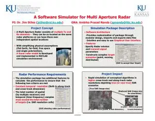
Overview of the IMPACT Project: Coordination and Development Journey
The IMPACT Project, led by David Curtis at UCB, encompasses a multi-institutional collaboration involving key teams and instruments including SEP, Boom, and others. With contracts in place across institutions like Caltech, GSFC, and others, the project has established a comprehensive development plan for subsystem testing and integration. The focus on milestone scheduling and performance requirements ensures that critical developments are monitored. Key instruments are strategically located on the spacecraft to achieve mission objectives, marking significant progress in space science research.

Overview of the IMPACT Project: Coordination and Development Journey
E N D
Presentation Transcript
IMPACT Project Overview David Curtis
Organization • IMPACT Suite managed by PI (Luhmann) and PM (Curtis) at UCB • SEP Team coordinated by von Rosenvinge at GSFC • Boom suite coordinated by Bob Lin at UCB • Instrument Hardware developed at Co-Investigator Institutions (lead institution and Co-I listed): • MAG at GSFC (Acuna) • SWEA at CESR (Sauvaud) • STE at UCB (Larson) • Boom at UCB (Ullrich) • IDPU at UCB (Curtis) • HET at GSFC (Tycho) • LET at Caltech (Mewaldt) • SEPT at Kiel (Mueller-Mellin) • SIT at University of Maryland (Mason) • SEP Common Electronics at Caltech (Mewaldt) David Curtis
Contracting • Project Contracts UCB • Phase A, Bridge contract complete • Phase B/C/D Contract in place • UCB Subcontracts Caltech/JPL, University of Maryland, LBNL, UCLA • Phase A, Bridge contract complete • Phase B/C/D subcontracts in place (?) • Modeler’s subcontracts on hold until closer to launch • GSFC funded directly by Project • Funding in place • Project contracts with LANL directly • Phase A, Bridge contract complete • Phase B/C/D contract in place (?) • CESR funded by CNES (France) • Funding in place • Kiel, Max Planck funded by DLR (Germany) • Funding in place • ESTEC funded by ESA • Funding in place David Curtis
Development Plan • Each subsystem will develop some level of ETU to prove the design concept • The different ETUs shall be tested together to verify interfaces • Most ETU testing will be complete by CDR • ETUs shall be maintained through the life of the mission to provide a test bed for changes • Flight unit assembly shall generally start following CDR • Long lead flight part procurement shall start following PDR • Subassemblies shall be functionally tested and calibrated at the home institution • Some environmental tests will be performed at the subassembly level, such as Vibration and Thermal Vacuum, on a case by case basis. • SEP subassemblies shall be integrated and tested at Caltech • Boom subassemblies shall be integrated and tested at UCB • The full suite will come together for EMC testing David Curtis
Schedule • Complex multi-institutional interlocking development effort • A top-level set of mile-stones marking the interactions between institutions has been developed • Lower-level schedules maintained by each institution, linked to the top level milestone schedule • Milestone schedule has been hierarchically divided into Top level and SEP • SEP deliveries to the rest of the team described on the top-level schedule • Deliveries internal to SEP described by the SEP milestone schedule • SEP Milestone schedule controlled by SEP team David Curtis
IMPACT Milestone Schedule David Curtis
SEP Milestone Schedule David Curtis
Schedule Analysis • The suite flight hardware first all come together at the EMC test. The pacing item in scheduling the EMC test is currently the SEP delivery from Caltech (following SEP calibration and thermal vac) • There are 7 weeks of slack in the SEP schedule prior to EMC • A number of subsystems pace the SEP development with similar amounts of slack: • The VLSI (ASIC) used in HET, LET, and SIT • The LET board • The LET MISC board • The SSD bias supply • SEP Firmware • There are 2 weeks of slack between EMC testing and delivery to the spacecraft • There is some distributed slack in the development effort based on conservative scheduling estimates David Curtis
SYSTEM ENGINEERING David Curtis
IMPACT Instrument Locations on the Spacecraft Ahead Spacecraft Behind Spacecraft SEPT-NS SEPT-NS SEPT-E STE-U STE-U LET LET HET HET SIT SIT SEPT-E IMPACT Boom IMPACT Boom MAG MAG STE-D STE-D SWEA SWEA David Curtis
IMPACT Instrument Locations on the Spacecraft Ahead Spacecraft Behind Spacecraft STE-U STE-U LET HET SIT LET HET SEPT-E SIT SEPT-NS SEPT-NS SEPT-E David Curtis
Boom Suite (Stowed) David Curtis
Boom Suite (Deployed) David Curtis
SEP HET/LET/SIT/Common Electronics SIT HET LET David Curtis
SEP/SEPT David Curtis
IDPU David Curtis
Instrument Requirements • Instrument Performance Requirements documented in IMPACTPerformanceSpec_E.doc • Instrument Interface & Resource Requirements documented in IMPACT/Spacecraft ICD • Environmental test requirements documented in 7381-9003 • Contamination Control requirements documented in 7381-9040 • EMC requirements documented in 7381-9030 • Mission Assurance Requirements based on Project System Safety Mission Assurance document, and implemented in IMPACT PAIP • Programatic requirements (deliverables, cost, schedule, etc.) covered in IMPACT contract David Curtis
MAG Performance Requirements • MAG addresses mission level 1 requirements: • 01.01.0002, CME Speed • 01.01.0003, CME Direction • 01.01.0008, Magnetic Field Measurement David Curtis
SWEA Performance Requirements • SWEA addresses mission level 1 requirements: • 01.01.0002, CME Speed • 01.01.0006, Solar Wind Temperature • 01.01.0007, Solar Wind Velocity • 01.01.0008, Solar Wind Magnetic Field • 01.01.0009, Solar Wind Density David Curtis
STE Performance Requirements • STE addresses mission level 1 requirements: • 01.01.0005, CME Initiation Location • 01.01.0006, Solar Wind Temperature • 01.01.0008, Solar Wind Magnetic Field • 01.01.0011, Energetic Particle Distribution Function David Curtis
SIT Performance Requirements • SEP (HET, LET, SEPT, and SIT) addresses mission level 1 requirements: • 01.01.0003, CME Direction • 01.01.0010, Location of Particle Acceleration • 01.01.0011, Energetic Particle Distribution Function, David Curtis
SEPT Performance Requirements David Curtis
LET Performance Requirements David Curtis
HET Performance Requirements David Curtis
Intra-Instrument Interfaces • Interfaces to IDPU documented by: • Serial Instrument Interface document covers the common hardware • IDPU Flight Software Requirements covers the software • Harness Specification covers harnesses between instruments • Documents controlled by UCB • Interfaces between SEP instruments covered: • SEP ICD covers electrical interface • SEP Software Development Plan covers software requirements • Documents controlled by Caltech • Interface to PLASTIC covered by: • Serial Instrument Interface document, controlled by UCB • PLASTIC Flight Software Requirements, controlled by UNH David Curtis
Resource Allocations David Curtis
IMPACT Block Diagram SEPT-NS SEP-Common LET HET SIT SEPT-E IDPU (Inside) MAG STE-D SWEA Color coded by circuit board in assemblies containing more than one board. David Curtis
IMPACT Harness Diagram David Curtis
IMPACT Grounding David Curtis
Configuration Control • Preliminary IMPACT Configuration Control Plan submitted • Problem reporting & Failure Review process described in IMPACT PAIP • Project to appoint a voting member of the IMPACT Failure Review Board • IMPACT will comply with Project-level CM Plan on Project-controlled documents (Class 1 changes) • IMPACT PM takes the lead role in interfacing with Project CM • Suite-level CM controlled by PM • Resources, Interfaces, Plans • Controlled documents maintained and controlled via a web site • PM controls changes at this level, as well as waiver/deviation process • Subsystem-level CM controlled by instrument lead engineers • Schematics, As-built drawings, Travelers, Flight Software • Subsystems come under Suite-level CM when delivered to integration David Curtis
Performance Assurance • IMPACT Performance Assurance Plan submitted to Project • Plan responds to the Project Mission Assurance Requirements Document • Plan covers all IMPACT Flight hardware/software and critical GSE development at all IMPACT institutions developing flight equipment • Mostly approved, pending an issue with Foreign CoI plan • Plan uses existing in-house procedures and practices (mostly based on NHB rather than ISO-9000) David Curtis
Contamination Control Plan • IMPACT PAIP includes a section on Contamination Control adequate for IMPACT requirements • Primarily a set of procedures with a proven track record • PAIP Includes standard materials outgassing requirements • Project Contamination Control Plan has additional requirements • Vacuum Bakeout • Surface Cleanliness • These requirements will be addressed mostly late in the I&T flow, with more relaxed requirements early, followed by cleaning and bakeout • IMPACT has Contamination Issues at the Observatory Level • All instruments are purged and have non-flight covers to protect sensitive detectors (some have in-flight deployable covers) • There is a concern about humidity and strong solvents, mostly taken care of by the purge, but some solvents will be forbidden near the instruments David Curtis
Top 10 Risks • Identified HIGH risk items have LOW probability of occurrence but HIGH Impact • 13 Additional Moderate and Low-score risks identified, not listed here • These risks are entered in the Project Risk Management Database • IMPACT Management team have taken the GSFC Risk Management course David Curtis
Trade Studies David Curtis