Download
1 / 12
120 likes | 311 Views
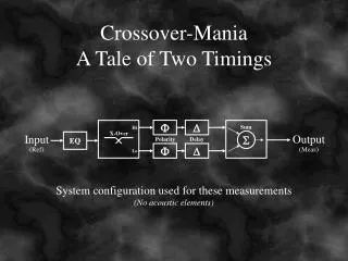
F. D. Sum. Hi. X-Over. Output. Input. S. EQ. Polarity. Delay. F. D. (Ref). (Meas). Lo. Crossover-Mania A Tale of Two Timings. System configuration used for these measurements (No acoustic elements). Symmetrical Crossover: 24 dB/oct L-R at 1kHz. +. X-Over. Sum. Hi. 0 ms.

E N D
F D Sum Hi X-Over Output Input S EQ Polarity Delay F D (Ref) (Meas) Lo Crossover-ManiaA Tale of Two Timings System configuration used for these measurements (No acoustic elements)
Symmetrical Crossover: 24 dB/oct L-R at 1kHz + X-Over Sum Hi 0 ms Output Input 24 dB/oct L-R S EQ Polarity Delay + (Ref) (Meas) 1 kHz Lo 0 ms Overlapping phase traces through crossover L-R Low-Pass L-R High-Pass Sum: Low-Pass + High-Pass L-R filters –6dB at xover Perfect summation through xover Two crossover filters measured separately. Two crossover filters summed back together
+ X-Over Sum Hi 0 ms Output Input 24 dB/oct L-R S EQ Polarity Delay + (Ref) (Meas) 1 kHz Lo 0 ms Filter Impulse Responses: Linear Views HPF Peak LPF Peak High-Pass Filter Note: If you simply used the AutoSm or Lg Impulse Resp measurements to measure the “driver” arrival times, you would be given the peak arrival times – and the peak of the LF is .5ms behind that of the HF. Low-Pass Filter
+ X-Over Sum Hi 0 ms Output Input 24 dB/oct L-R S EQ Polarity Delay + (Ref) (Meas) 1 kHz Lo 0 ms Filter Impulse Responses: Log & ETC Views HPF Peak LPF Peak Log View ETC: High-Pass Filter ETC: Low-Pass Filter
Delay Added to High Filter to Align Peaks in Time High-Pass Filter Low-Pass Filter + X-Over Sum Hi 0.5 ms Output Input 24 dB/oct L-R S EQ Polarity Delay + (Ref) (Meas) 1 kHz Lo 0 ms
Adjusted Timing Causes Cancellation at Crossover Phase traces 180° out at crossover L-R Low-Pass L-R High-Pass Sum: Low-Pass + High-Pass Cancellation at xover! + X-Over Sum Hi 0.5 ms Output Input 24 dB/oct L-R S EQ Polarity Delay + (Ref) (Meas) 1 kHz Lo 0 ms
Inverting Polarity of Low Filter Shifts Phase Trace 180° Phase traces 180° out at crossover Phase traces in phase at crossover + X-Over Sum Hi 0.5 ms Output Input 24 dB/oct L-R S EQ Polarity Delay - (Ref) (Meas) 1 kHz Lo 0 ms
The Result is Addition Through Crossover Addition at crossover not “perfect” + X-Over Sum Hi 0.5 ms Output Input 24 dB/oct L-R S EQ Polarity Delay - (Ref) (Meas) 1 kHz Lo 0 ms
EQ Applied to Flatten Response at Crossover EQ improves magnitude and phase responses Addition at crossover not “perfect” + X-Over Sum Hi 0.5 ms Output Input 24 dB/oct L-R S EQ Polarity Delay - (Ref) (Meas) 1 kHz Lo 0 ms