Download
1 / 32
320 likes | 440 Views
RF System for Bunch Rotation. C. Ohmori ( KEK). Contents. PRISM RF Introductions Present status RF for 6 cell ring Upgrade plan High Duty RF system for FFAG Medical application Experiences from J-PARC. Requirements for RF. High voltage at 3.8 MHz Total 2-3 MV 200 kV/m

E N D
RF System for Bunch Rotation C. Ohmori (KEK)
Contents • PRISM RF • Introductions • Present status • RF for 6 cell ring • Upgrade plan • High Duty RF system for FFAG • Medical application • Experiences from J-PARC
Requirements for RF • High voltage at 3.8 MHz • Total 2-3 MV • 200 kV/m • 8 straights for RF
Requirements for RF • Saw-Tooth RF • Linear RF bucket • Composed of 3 harmonics
MA cavity for PRISM • High field gradient at low frequency • Wideband (low Q) • Thin cavity (about 30 cm / cavity ) • Use the maximum size for MA cores (1.7m X 1m) • Very low duty RF system • Small tetrodes for the end stage • Small APS (anode power supply)
High Field Gradient : around 200 kV/m few MV RF for quick phase rotation (around 1.5 us) Dedicated system for pulse operation (low duty : 0.1%)
Characteristics of Magnetic Cores Ferrites シャントインピーダンスに比例 High Loss Effect 200V/div, 5ms/div 2000 Gauss Magnetic Alloys 電圧に比例
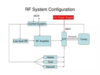
Dedicated system for low duty • AMP • Use small tubes • Works for short moment; 1-2 us X 1 kHz • For 1 kHz repetition, need to minimize RF-ON time • 99 % of time: zero anode current, 99.9%:zero RF output • Cavity loss : few kW • Tube loss : few ten kW • APS • Old fashion to minimize cost: Crowbar, 3-phase Full-wave rectification • J-PARC :1MW system, no crowbar, switching with IGBT • Supplies power to 4 AMPs, several MW in total.
Cathode current RFON Tube ON
Dedicated RF system for low duty J-PARC 600kW tube AMP 500kW output 1.4X1.0X2.4m 100kW tube AMP, >1MW output 1.4X0.7X0.8m APS for J-PARC, 4.5X2X2.7m APS, 1X1.5X2.0m
STATUS of PRISM RF • RF frequency 5 -> 3.8 MHz (larger circumference) • Tested at 2-3 MHz with a test cavity • Achieved 42 kV/gap by test cavity • Tube AMP:60A(design value)->70A as a RF current @ 2-3MHz • Cavity shroud is completed. Start to install cores. • Core impedance : about 135 W/core@3.5MHz • Number of cores: 4 instead of 6 (design : 6 cores, total 1kW)
6 cell PRISM • Test using a beam • 1(or 2,3) MHz, 100 kV/m • Saw-tooth • PRISM • 3.5 MHz, about 200 kV/m • Saw-tooth • Upgrade Plan • Cost, Higher field gradient
6 Cell ring • To test bunch rotation using a beam • Low energy, low RF frequency • Few ten kV is required to observe bunch motion. • Problems • Low impedance@ low frequency because of uncut cores • Expected voltage @1MHz : 352 W X 60 A= 21 kV • A Solution : use 2 RF AMPs to drive 1 cavity. • Expected voltage : 352 X 120 A =42 kV to prove 100kV/m Another solution : use parallel inductor scheme established through J-PARC R&D for high frequency.
Hybrid RF system • Proposed by A. Schnase. • Combination of MA cavity with a resonant circuit composed by inductor and capacitor. • Developed for J-PARC RCS cavities. f=1/2p√LC 1/L=1/Lcore+1/Lind Q=Rp/wL Rp: shunt J-PARC: add C and L to control Q and f PRISM : add L to control f
Parallel inductor for J-PARC Inside of PRISM AMP
Expected impedance with parallel inductor Total C =200pF Hybrid (+30uH inductor) Total C =100pF Hybrid (13 uH)
PRISM CAVITY for 6 cell ring • 4 Cores, around 3 MHz • Expected cavity impedance : 500 W • More than 35 kV (>100kV/m) seems possible (70A X 500 W).
Saw-Tooth : Dual Drive System • RF Cavity will be a wideband cavity. • But, bandwidth of AMP is still limited (1/RC). • To obtain high RF voltage, a large drive voltage is required for CG-Cathode. • Usually, AMP is driven from CG or Cathode. • Drive from both CG and Cathode is possible in case of short pulse operation. • Narrow bandwidths are enough for both CG and Cathode. -> save the cost for Driver AMP • But, need test.
Upgrade Plan • High Field Gradient • Cost reduction
Improvements of cavity impedance • Hybrid cavity with ceramic cavity • Improvements of cavity cores • X 2 by annealing under magnetic field for thinner ribbon • Small cores : OK • Large core ?
How to improve • MA consists of Fe, Si, B, Cu and Nb. • Amorphous ribbon (<20 mm) is annealed and crystallized. • Combination of magnetic field during annealing and thinner ribbon (13 mm) • The small crystal has an axis magnetized easily. By the special annealing, the axis is equal. • But relation between core impedance and this effect is not clear. • Small cores : proved by Hitachi Metal • Large core : need big magnet and special oven. => Appling FY2007 JSPS grant to produce these special core in KEK. B-H curve of MA core produced by annealing with/without magnetic field. (by Hitachi Metal)
Ceramic Cavity • Proposed by J. Griffin. • Low frequency air core cavity with a ceramic capacitor to resonate. • Titanium Oxide capacitor was tested. 50kVDC (tested with 60kVDC). 1200pF. Electrodes are O.D. 121mmX I.D. 52mm, Thickness of ceramic is 14mm. • Supported by JSPS money. Purpose : bunch rotation with low rep. rate. • Small test cavity :30 cm X 30cm • 4 kW, Q=700, fres=7 MHz • High power test is planned. • High rep. rate : Hybrid cavity system with MA cavity. • Effective Q => below 100.
conclusions • We start assembling PRISM rf cavity • Demonstrate > 100 kV/m in April/May • Also plan to test saw-tooth RF • For general application, design of FFAG cavity is presented.
High duty RF system for FFAG • General applications (beam acceleration ) • High duty (100 %) • Preliminary design based on experiences at the J-PARC ring RF • Direct water cooling • High average power
Direct Water Cooling • Effective Cooling Scheme • Adopted for J-PARC Ring RF • 1W/cc, more than 1000 H test run • COSY, CERN-LEIR, HIMAC-MA • Design for FFAG cavity
Power Consumption for FFAG cavity • 10MeV->140 MeV • 1.5->4 MHz • 6 kV/gap, 100 % duty • 4 X PRISM-size cores • 1.7 m X 1m X 3cm • Size of Cavity :2m X 1.2 m X 0.4-0.5 m • 45 kW/gap, 11.25 kW/core • 0.32W/cc (av.), 0.54 W/cc (Max.) < 1 W/cc
Technical key issues • Good immersion • Mechanical strength • Cause of pin holes • Good coating • J-PARC : epoxy+glass fiber • Careful treatment of core surface • Scratch of MA surface may make local hot spots, destroy coating and reduce core impedance • Dusts on MA surface may make very local hot spots and destroy coating